11-3
11. HYDRAULIC SYSTEM
SA221/324/424 Operation Manual
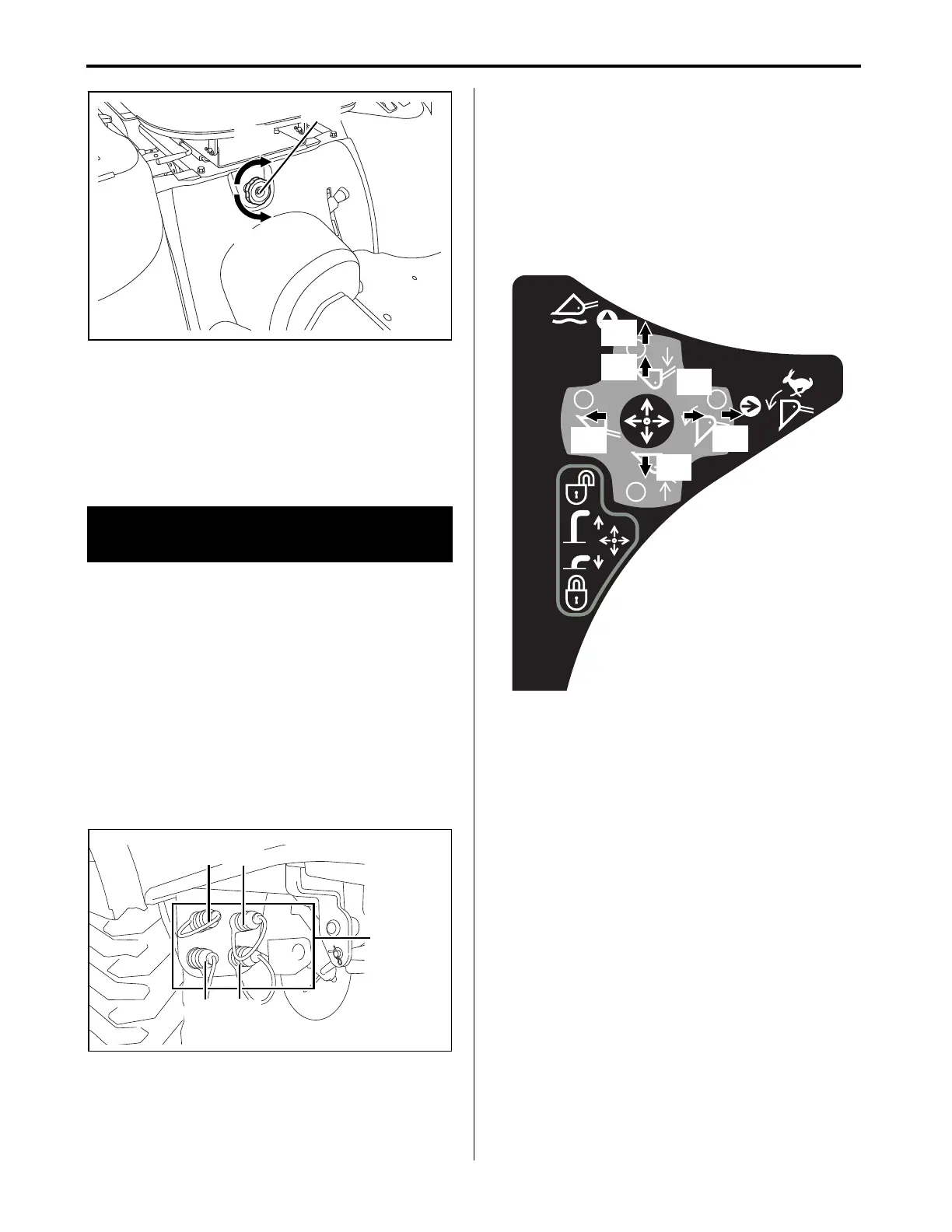
(A) Hydraulic flow control/stop knob
(a) Knob turned counterclockwise:
• increases the rate of drop speed
• unlocks the hydraulic lift
(b) Knob turned clockwise:
• decreases the rate of drop speed
Knob turned clockwise until the knob stops
turning:
• locks the hydraulic lift
■ Implement Control Lever
1. Use the implement control lever to operate the
optional mounted implements.
2. There are 4 hydraulic quick couplers (color coded
by the rubber plugs).
• The hydraulic quick couplers are located under
the right foot deck.
• The hydraulic quick couplers are used to connect
the tractor's hydraulics to the implement's
hydraulic cylinders.
3. Use the hydraulic quick couplers in pairs: 1 & 3
and 2 & 4.
(A) Hydraulic quick couplers
(1) Yellow
(2) Blue
(3) Green
(4) Red
4. After the hydraulic quick couplers and hydraulic
lines have been connected, the attached
implement moves in a direction opposite to the
expected direction:
• Interchange the hydraulic line connections
between couplers 1 & 3.
• Interchange the hydraulic line connections
between couplers 2 & 4.
(a) Lower
(b) "Float"
(c) Dump
(d) Dump faster
(e) Raise
(f) Curl
2. Operate the Implement Control
Valve
B1
B2
A2
A1
SA221_324_424_OperatorsManual.book 3 ページ 2018年6月4日 月曜日 午後5時19分
 Loading...