(3) Cooling System Installation
Use the following calculation formula to select a cooling system and install it in the control panel so that the
air temperature in the control panel will be no more than 10°C higher than the reference value.
∆T = =
• ∆T: Temperature rise in the control panel (°C)
•P: Calorific value in the control panel (W)
•qe: Heat flow through ratio of the control panel (W/°C)
•qh: Heat flow through ratio of the cooling system(W/°C)
•k: Heat pass through ratio of a metal plate (W/m
2
°C)
With a stirring fan:
6 W/m
2
°C
Without a stirring fan
:
4 W/m
2
°C
•A: Effective radiation area of the control panel (m
2
)
*
•B: Installation area of the cooling system (m
2
)
∗ Radiation available area of the control panel surface area (Exclude the surface which contacts other object)
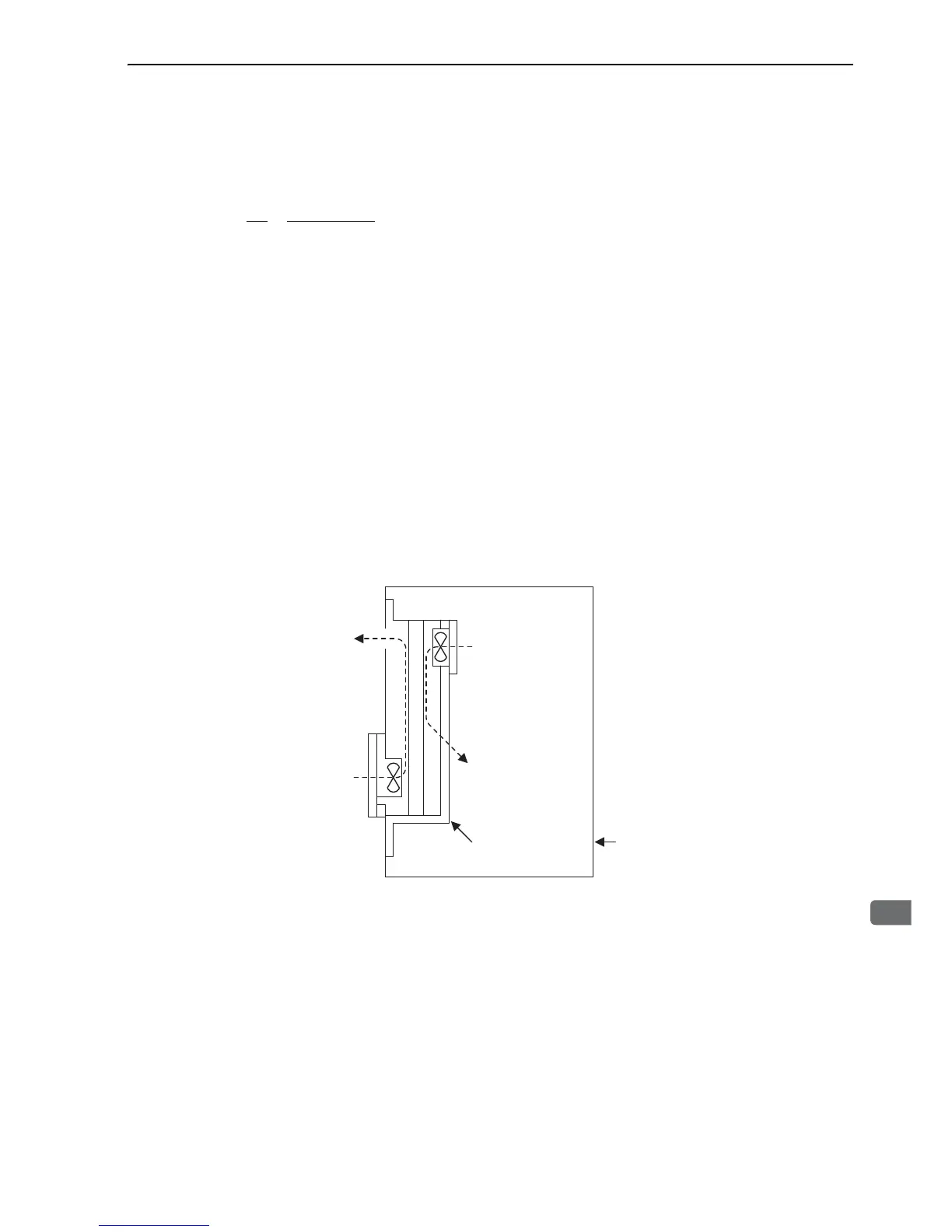
An installation example is given below.
Install the cooling system so that internal air is taken into the control panel at the top and returned at the bot-
tom, and so that the external air is taken in at the bottom and exhausted at the top.
Cooling System Installation
 Loading...


