Inverter SIO Driver
GP-Pro EX Device/PLC Connection Manual
61
6 Supported Device
The following table shows the range of supported device addresses. Please note that the actually supported range
of the devices varies depending on the External Device to be used. Please check the actual range in the manual of
your External Device.
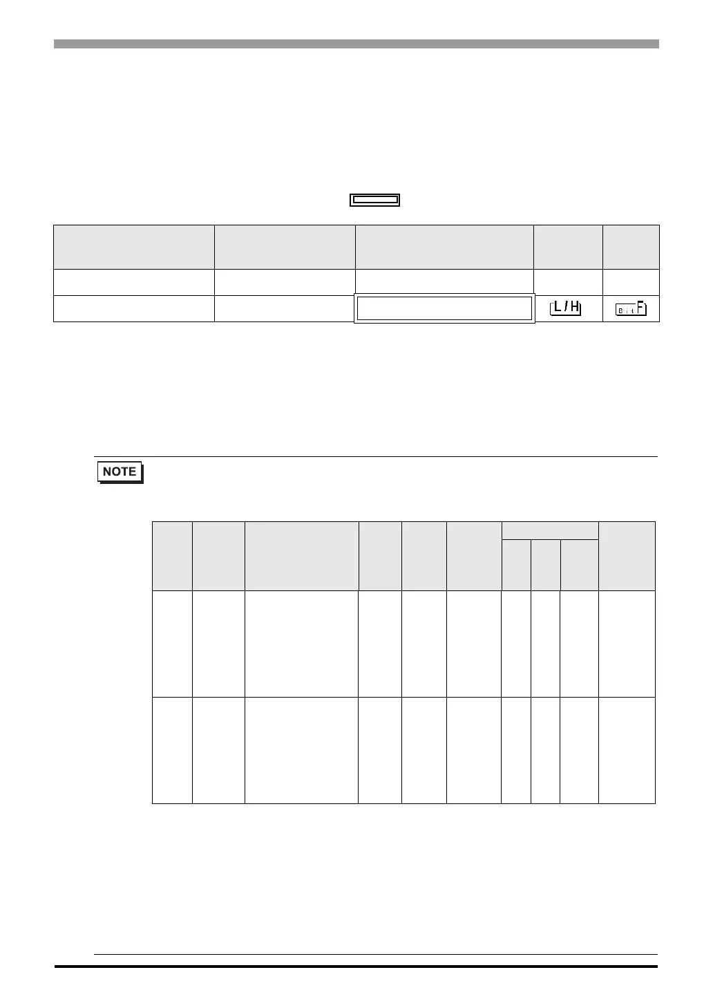
: This address can be specified as system data area.
Device Bit Address Word Address 32 bits
Remar
ks
Bit Register
*1
*1 The Bit Register and the Register are the same device, but their bit write operation differs. Use either as needed.
BR0000.0 - BR1959.F ------ -
*2
*2 When bits are written, the Display reads the corresponding word address from the External Device, sets
particular bits of that word address to ON, and then returns the resulting address to the External Device. Note
that the correct data may not be written if you change the word address using the ladder program while the
Display reads data from the External Device and returns it. To write bits to the write-only register, use a
registering device. Writing bits to the write-only register will cause a communication error to appear when the
readout command is executed.
Register
*1
------ 0000 - 1959
• If you use a device, set the address to the MEMOBUS register No. corresponding to the parameter
No. Refer to your External Device manual for details.
• You can only set the Read Area Size for the system area available to use in the External Device.
Please refer to the GP Pro-EX Reference Manual for Read Area Size.
• Refer to the GP-Pro EX Reference Manual for system data area.
Cf. GP-Pro EXReference Manual "Appendix 1.4 LS Area (Direct Access Method)"
• For the icons in the table, refer to the notes on manual notation.
)"Manual Symbols and Terminology"
Example) Correspondence between the Inverter Constant Number and MEMOBUS register
Constant
No.
Name Description
Setting
Range
Default
Value
Changes
during
Operation
Control mode
MEMOBUS
Register
V/f
with-
out
PG
V/f
with
PG
Vector
without
PG
A1-02
Selection of
Control
Mode
Select an inverter control
mode.
0: V/f control without PG
1: V/f control with PG
2: Vector control without
PG
The control mode is not
initialized by selecting
INITIALIZE.
0 to 2 0 × Q Q Q 102H
b1-01
Selection of
frequency
command
Select a frequency
command input method.
0: Digital operator
1: Control circuit terminal
(analog input)
2: MEMOBUS
communication
3: Optional card
4: Pulse column input
0 to 4 1 × Q Q Q 180H
 Loading...