661693-UIM-E-1212
8 Johnson Controls Unitary Products
SECTION VI: LOW VOLTAGE CONTROL
CONNECTIONS
The 24 volt power supply is provided by an internally wired low voltage
transformer which is standard on all models, However, if the unit is con-
nected to a 208 volt power supply, the low voltage transformer must be
rewired to the 208 volt tap. See the unit wiring label.
Field supplied low voltage wiring can exit the unit on the top right hand
corner or the right hand side panel. Refer to Figure 2.
Remove desired knockout and pierce foil faced insulation to allow wir-
ing to pass through. Use as small of a hole as possible to minimize air
leakage. Install a 7/8” plastic bushing in the selected hole and keep low
voltage wiring as short as possible inside the control box.
To further minimize air leakage, seal the wiring entry point at the outside
of the unit.
The field wiring is to be connected at the pigtails supplied with the con-
trol board harness. Refer to SECTIONS X and XI for system wiring.
SECTION VII: BLOWER SPEED
CONNECTIONS
Adjust blower motor speed to provide airflow within the minimum and
maximum limits approved for evaporator coil, electric heat and outdoor
unit. Speed tap adjustments are made at the motor terminal block. Air-
flow data is shown in Table 10.
Connect motor wires to motor speed tap receptacle for speed desired.
See unit wiring label for motor wiring details.
SECTION VIII: UNIT DATA
All wiring must comply with local and national electrical code require-
ments. Read and heed all unit caution labels.
It is possible to vary the amount of electric heat turned on during the
defrost cycle of a heat pump. Standard wiring will only bring on the
first stage of electric heat during defrost. See Table 5 for additional
information on heat during defrost cycle.
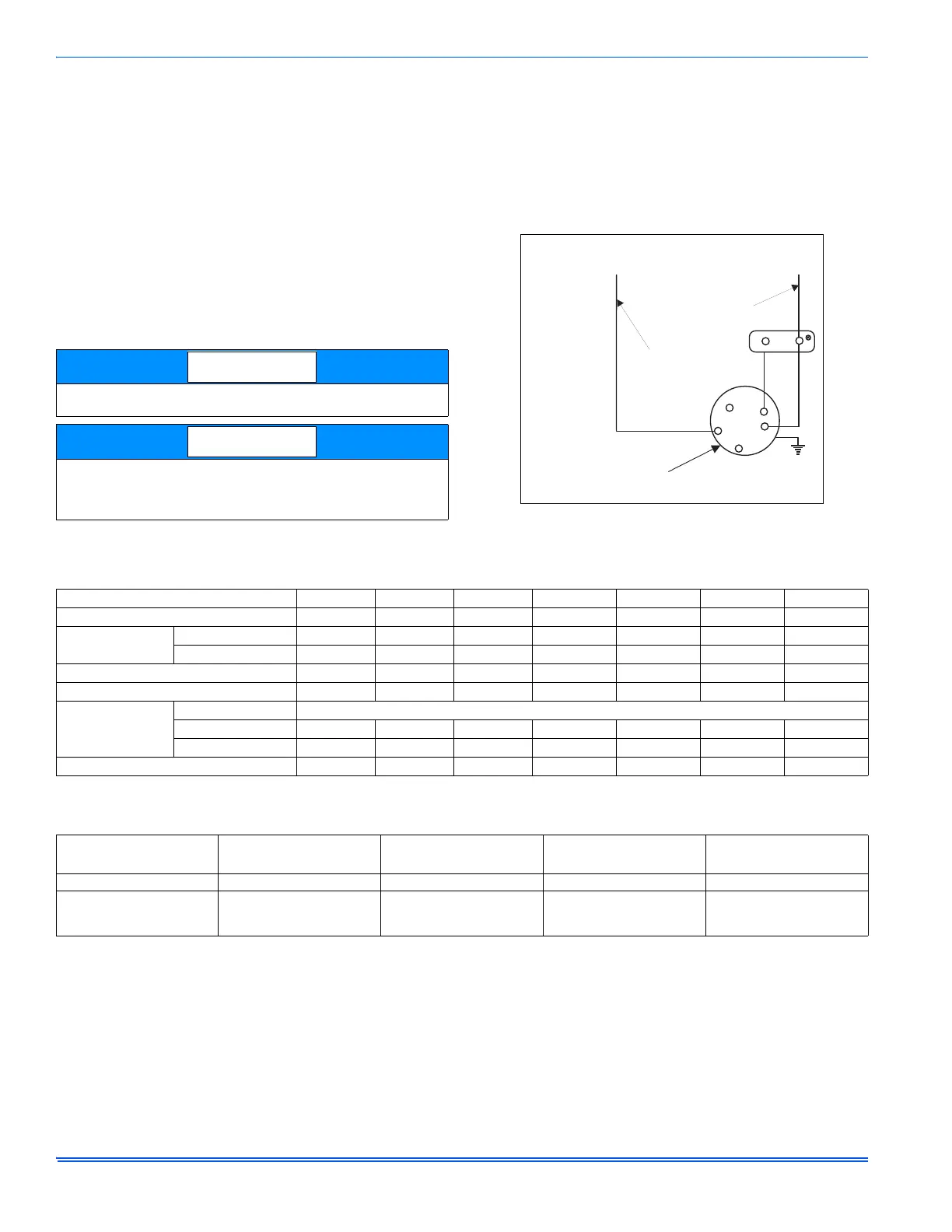
FIGURE 14: Blower Speed Connections
FACTORY WIRED TO
TRANSFORMER
FACTORY WIRED TO
FAN MOTOR RELAY
TERMINAL ON
CONTROL BOARD
PUR
PUR
HIGH
MED
LOW
GND.
230 VOLT
BLOWER MOTOR
AHR STANDARD MOTOR
CAP
BRN
BLK
TABLE 2:
Physical and Electrical Data
Models AHR18B AHR24B AHR30B AHR36B AHR42C AHR48D AHR60D
Blower - Diameter x Width 10 x 8 10 x 8 10 x 8 10 x 8 10 x 10 10X10 10X10
Motor
HP 1/4 HP 1/4 HP 3/4 HP 3/4 HP 3/4 HP 3/4 HP 3/4 HP
Nominal RPM 1075 1075 1075 1075 1075 1075 1075
Voltage 208/230 208/230 208/230 208/230 208/230 208/230 208/230
Full Load Amps @230V
1.4 1.4 3.0 3.0 3.0 3.0 3.0
Filter
1
Type DISPOSABLE OR PERMANENT
Size 16 x 20 x 1 16 x 20 x 1 16 x 20 x 1 16 x 20 x 1 20 x 20 x 1 22 x 20 x 1 22 x 20 x 1
Permanent Type Kit 1PF0601BK 1PF0601BK 1PF0601BK 1PF0601BK 1PF0602BK 1PF0603BK 1PF0603BK
Shipping / Operating Weight (lbs.) 112/100 117/102 117/105 122/110 148/133 165/147 168/150
1. Field Supplied.
TABLE 3:
Electrical Data - Cooling Only
Models
Motor FLA
1
Minimum Circuit Ampacity
MOP
2
Minimum Wire Size
(AWG)
3
AHR18B / AHR24B 1.4 1.8 15 14
AHR30B / AHR36B /
AHR42C / AHR48D /
AHR60D
3.0 3.8 15 14
1. FLA = Full Load Amps
2. MOP = Maximum Overcurrent Protection device; must be HACR type circuit breaker or time delay fuse.
3. 75C, copper wire only. If wire other than non-plated, 75C ambient, copper wire is used, consult applicable tables of the NEC and local codes..
 Loading...