Johnson Controls Unitary Products 5
5151060-YTG-F-1116
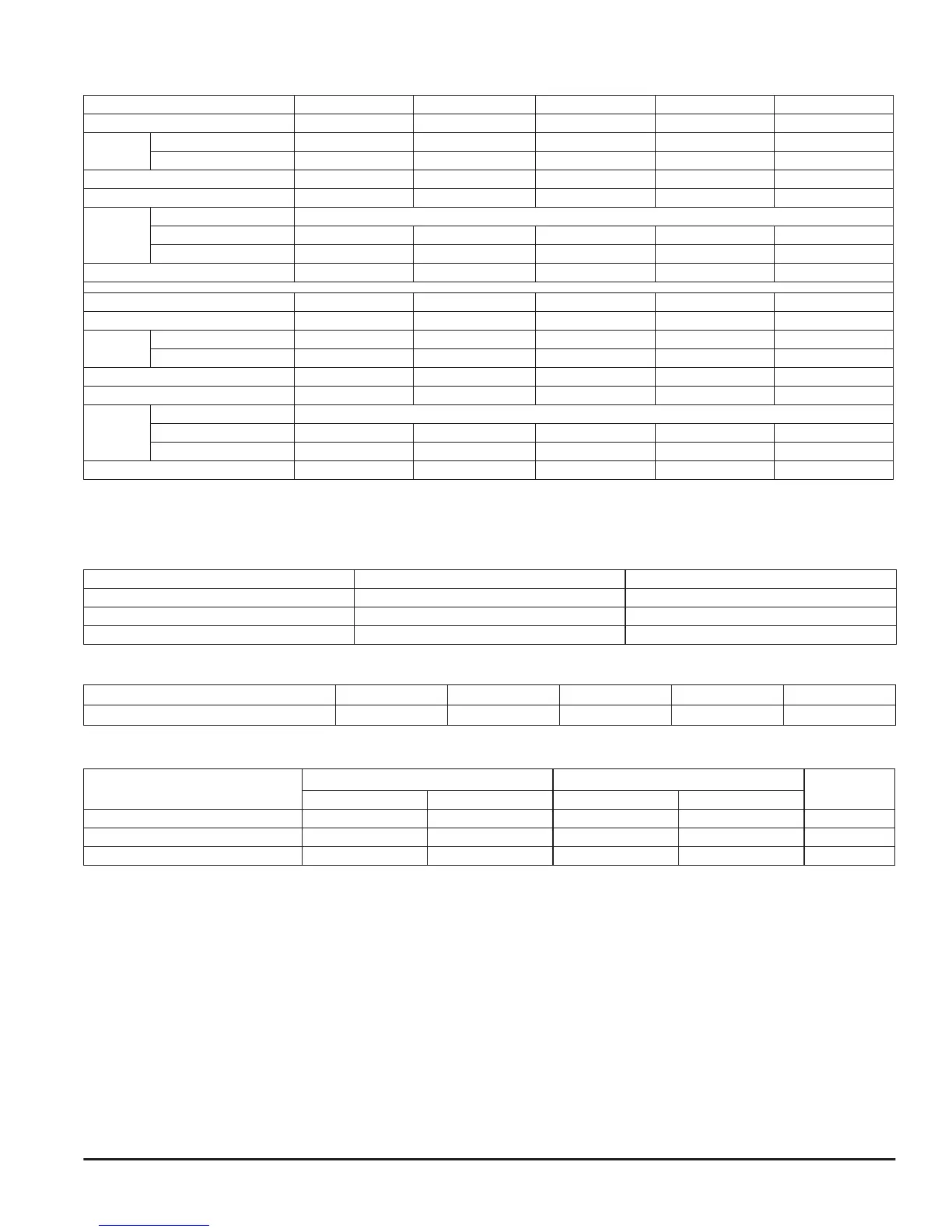
PHYSICAL & ELECTRICAL DATA - COOLING ONLY
Models 18B 24B 30B 36B 36C
Blower - Diameter x Width 10 x 8 10 x 8 10 x 8 10 x 8 11 x 10
Motor
HP 1/3 HP 1/3 HP 1/3 HP 1/2 HP 1/2 HP
Nominal RPM 1050 1050 1050 1050 1050
Voltage 208/230 208/230 208/230 208/230 208/230
Full Load Amps @230V 2.9 2.9 2.9 4.5 4.5
Filter
1
Type DISPOSABLE OR PERMANENT
Size 16 x 20 x 1 16 x 20 x 1 16 x 20 x 1 16 x 20 x 1 20 x 20 x 1
Permanent Type Kit 1PF0601 1PF0601 1PF0601 1PF0601 1PF0602
Shipping Operating Weight (lbs.) 91/85 93/87 119/113 119/113 120/114
Models 42C 48C 48D 60C 60D
Blower - Diameter x Width 11 x 10 11 x 10 11 x 10 11 x 10 11 x 10
Motor
HP 1/2 HP 3/4 HP 3/4 HP 3/4 HP 3/4 HP
Nominal RPM 1050 1050 1050 1050 1050
Voltage 208/230 208/230 208/230 208/230 208/230
Full Load Amps @230V 4.5 7.0 7.0 7.0 7.0
Filter
1
Type DISPOSABLE OR PERMANENT
Size 20 x 20 x 1 20 x 20 x 1 22 x 20 x 1 20 x 20 x 1 22 x 20 x 1
Permanent Type Kit 1PF0602 1PF0602 1PF0603 1PF0602 1PF0603
Shipping Operating Weight (lbs.) 144/136 158/150 163/153 156/146 180/170
1. Field supplied.
kW & MBH CONVERSIONS - FOR TOTAL POWER INPUT REQUIREMENT
For a power distribution voltage that is different than the provided nominal voltage, multiply the kW and MBH data from the table by the conversion
factor in the following table.
DISTRIBUTION POWER NOMINAL VOLTAGE CONVERSION FACTOR
208V 240V 0.75
220V 240V 0.84
230V 240V 0.92
APPLICATION FACTORS - RATED CFM VS. ACTUAL CFM
% Of Rated Airflow (CFM)
80% 90% 100% 110% 120%
Capacity Factor
0.96 0.98 1.00 1.02 1.03
ELECTRICAL DATA - COOLING ONLY
Models
Motor FLA
1
Minimum Circuit Ampacity
MOP
2
208V 230V 208V 230V
18B/24B/30B 3.0 2.9 3.8 3.6 15
36B/36C/42C 5.0 4.5 6.3 5.6 15
48C/48D/60C/60D 7.3 7.0 9.1 8.8 15
1. FLA = Full Load Amps
2. MOP = Maximum Overcurrent Protection device; must be HACR type circuit breaker or time delay fuse. Refer to the latest edition of the
National Electric Code or in Canada the Canadian electrical Code and local codes to determine correct wire sizing.
 Loading...