SERVICE ACCESS
Access to all serviceable components is provided by the follow
-
ing removable panels:
•
Blower service access
•
Electrical/Filter access
•
Compressor service access
Refer to Figure 3 for location of these access panels and mini
-
mum clearances.
THERMOSTAT
The room thermostat should be located on an inside wall ap
-
proximately 56" above the floor where it will not be subject to
drafts, sun exposure or heat from electrical fixtures or appli
-
ances. Follow manufacturer's instructions enclosed with the
thermostat for general installation procedure. Six color coded
insulated wires (minimum #18 AWG) should be used to con
-
nect thermostat to unit. See Figure 2.
POWER AND CONTROL WIRING
Field wiring to the unit must conform to provisions of the cur
-
rent N.E.C. ANSI/NFPA No. 70 or C.E.C. and/or local ordi
-
nances. The unit must be electrically grounded in
accordance with local codes or, in their absence, with the
N.E.C./C.E.C. Voltage tolerances which must be maintained
at the compressor terminals during starting and running con
-
ditions are indicated on the unit Rating Plate and Table 3.
The wiring entering the cabinet must be provided with me
-
chanical strain relief.
A fused disconnect switch should be field provided for the unit.
If any of the wire supplied with the unit must be replaced, re
-
placement wire must be of the type shown on the wiring dia
-
gram.
Electrical line must be sized properly to carry the load. Each
unit must be wired with a separate branch circuit fed directly
from the meter panel and properly fused.
Refer to Figure 2 for typical field wiring and to the appropriate
unit wiring diagram for control circuit and power wiring informa
-
tion.
COMPRESSORS
Units are shipped with compressor mountings factory-
adjusted for shipping. Caution: Loosen compressor bolts
half turn before operating unit.
.
035-16004-001-A-0202
4 Unitary Products Group
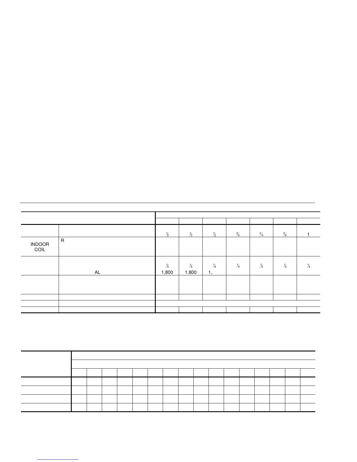
TABLE 2 - PHYSICAL DATA
MODELS
BHA
018 024 030 036 042 048 060
INDOOR
BLOWER
CENTRIFUGAL BLOWER (Dia. x Wd. in.) 9 X 6 10 X 8 10 X 8 10 x 8 11 X 10 11 X 10 11 X 10
FAN MOTOR HP (Three Speed)
1
2
1
2
1
2
3
4
3
4
3
4
1
INDOOR
COIL
ROWS DEEP 2233333
FINS PER INCH 15 13 13 15 15 16 16
FACE AREA (Sq. Ft.) 4.38 4.38 4.38 4.38 4.38 5.62 5.62
OUTDOOR
FAN
PROPELLER DIA. (in.) 22 22 22 22 22 22 22
FAN MOTOR HP
1
4
1
4
1
4
1
4
1
4
1
4
1
4
NOM. CFM TOTAL 1,800 1.800 1,800 2,400 2,400 2,800 2,800
OUTDOOR
COIL
ROWS DEEP 1111111
FINS PER INCH 20 20 20 20 20 16 20
FACE AREA (Sq. Ft.) 8.3 11.7 11.7 11.7 11.7 16.4 16.4
CHARGE REFRIGERANT 22 (lbs./oz.) 4 / 12 5 / 12 7 / 8 5 / 5 5 / 5 9 / 0 10 / 0
FILTER FACE AREA (Sq. Ft. / Qty. / Size) 4.28 / 2 / 14" x 22"
COMPRESSOR HERMETIC Type, (Qty. = 1)
Reciprocating Reciprocating Scroll Scroll Scroll Scroll Scroll
TABLE 3 - ADDITIONAL STATIC PRESSURE RESISTANCE
DISCRIPTION
RESISTANCE, IWG
CFM
500 600 700 800 900 1,000 1,100 1,200 1,300 1,400 1,500 1,600 1,700 1,800 1,900 2,000
Wet Indoor coil 0.01 0.01 0.01 0.02 0.02 0.03 0.03 0.04 0.04 0.04 0.04 0.04 0.05 0.05 0.06 0.07
Economizer 0.00 0.00 0.00 0.01 0.01 0.01 0.01 0.02 0.03 0.04 0.05 0.06 0.07 0.07 0.08 0.08
Filter/Frame Kit 0.01 0.02 0.02 0.02 0.02 0.02 0.03 0.03 0.03 0.03 0.04 0.05 0.05 0.06 0.06 0.07
Electric Heat 0.02 0.03 0.03 0.03 0.04 0.04 0.05 0.06 0.07 0.08 0.09 0.10 0.01 0.11 0.11 0.12
NOTE: 1. Deduct these resistance values from the available external static pressure shown in the respective Blower Performance Table.
2. The pressure thru the economizer is greater for 100% outdoor air then for 100% return air. If the resistance of the return air duct system is less then 0.25 IWG, the unit will deliver
less CFM during full economizer operation.