Cont’d.
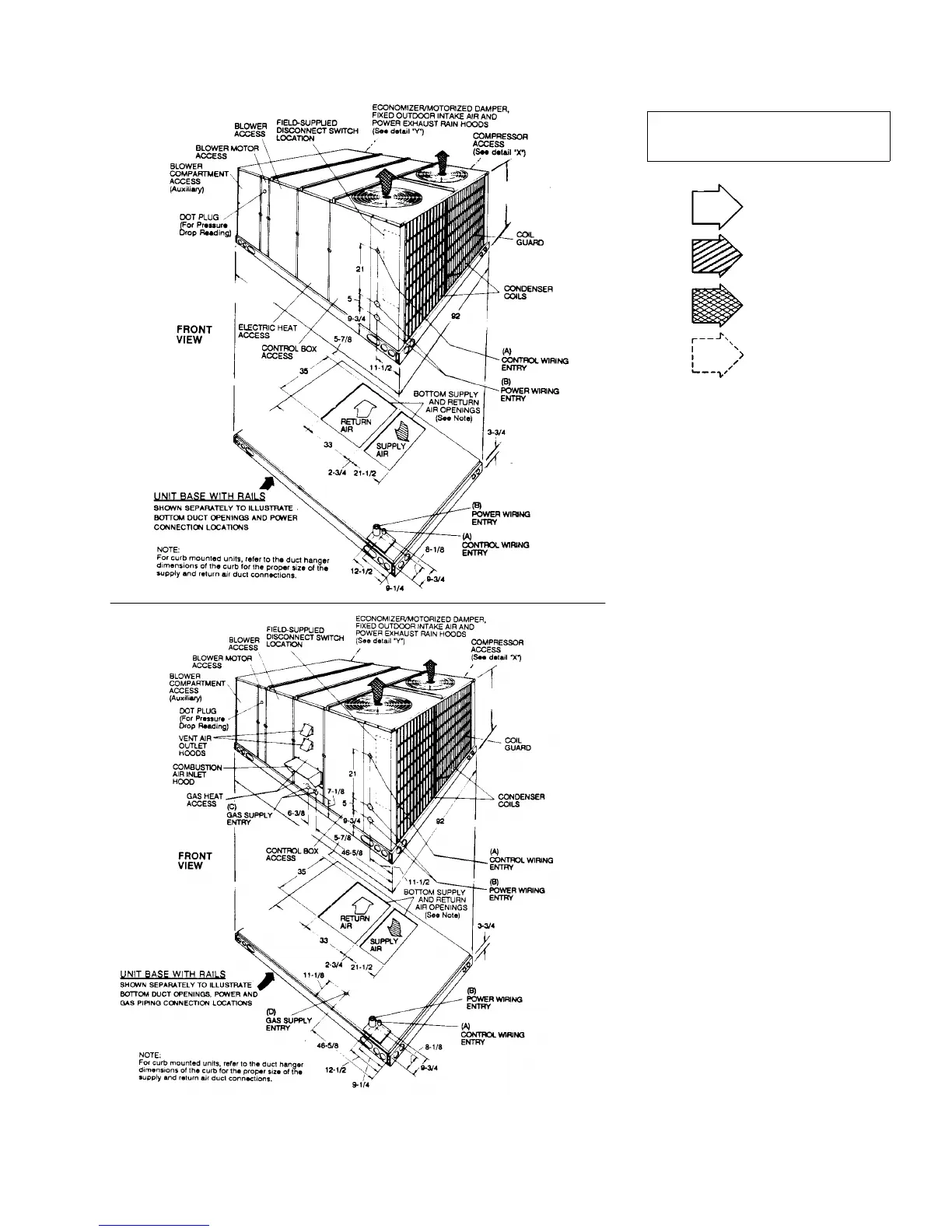
FIG. 10 - DIMENSIONS & CLEARANCES - DCE & DCG
All dimensions are in inches. They are sub-
ject to change without notice. Certified di-
mensions will be provided upon request.
CLEARANCES
Front 36"
Back
24" (Less Economizer)
49" (With Economizer)
Left Side (Filter Access)
24" (Less Economizer)
54" (With Economizer)
Right Side (Cond. Coil) 36"
Below Unit
1
20"
Above Unit
2
72" With 36" Maximum
Horizontal Overhang
(For Condenser Air
Discharge)
1
Units (applicable in U.S.A. only) may be installed on combustible floors
made from wood or class A, B or C roof covering material.
2
Units must be installed oudoors. Overhanging structures or shrubs should
not obstruct condenser air discharge outlet.
NOTE:
DCE Models: Units and ductwork are approved for zero clearance to combus-
tible materials when equipped with electric heaters.
DCG Models: A 1" clearance must be provided between any combustible
material and the supply air ductwork for a distance of 3 feet from the unit.
The products of combustion must not be allowed to accumulate within a
confined space and recirculate.
Locate unit so that the vent air outlet hood is at least:
• Three (3) feet above any forced air inlet located within 10 horizontal feet
(excluding those integral to the unit).
• Four (4) feet below, 4 horizontal feet from, or 1 foot above any door or gravity
air inlet into the building.
• Four (4) feet from electric meters, gas meters, regulators and relief equip-
ment.
HOLE
OPENING
SIZE
(DIA.)
USED FOR
A
1-1/8" KO
Control
Wiring
Front
3/4" NPS (Fem.) Bottom
B
3-5/8" KO
Power
Wiring
Front
3" NPS (Fem.) Bottom
C 2-3/8" KO Gas Piping (Front)
D 1-11/16" Hole Gas Piping (Bottom)*
*
Opening in the bottom of the unit can be located by the slice
in the insulation.
UTILITIES ENTRY DATA
RETURN AIR
SUPPLY AIR
CONDENSER AIR
OUTDOOR AIR
(Economizer)
DCE
UNITS
52-5/8
136-1/4
35-1
/4
DCG
UNITS
52-5/8
136-
1/4
35
-1/4
530.18-N11Y
Unitary Products Group 11

 Loading...