10 Unitary Products Group
035-16192-001-A-1001
COPPER
2SCREWS
CORNER
POST
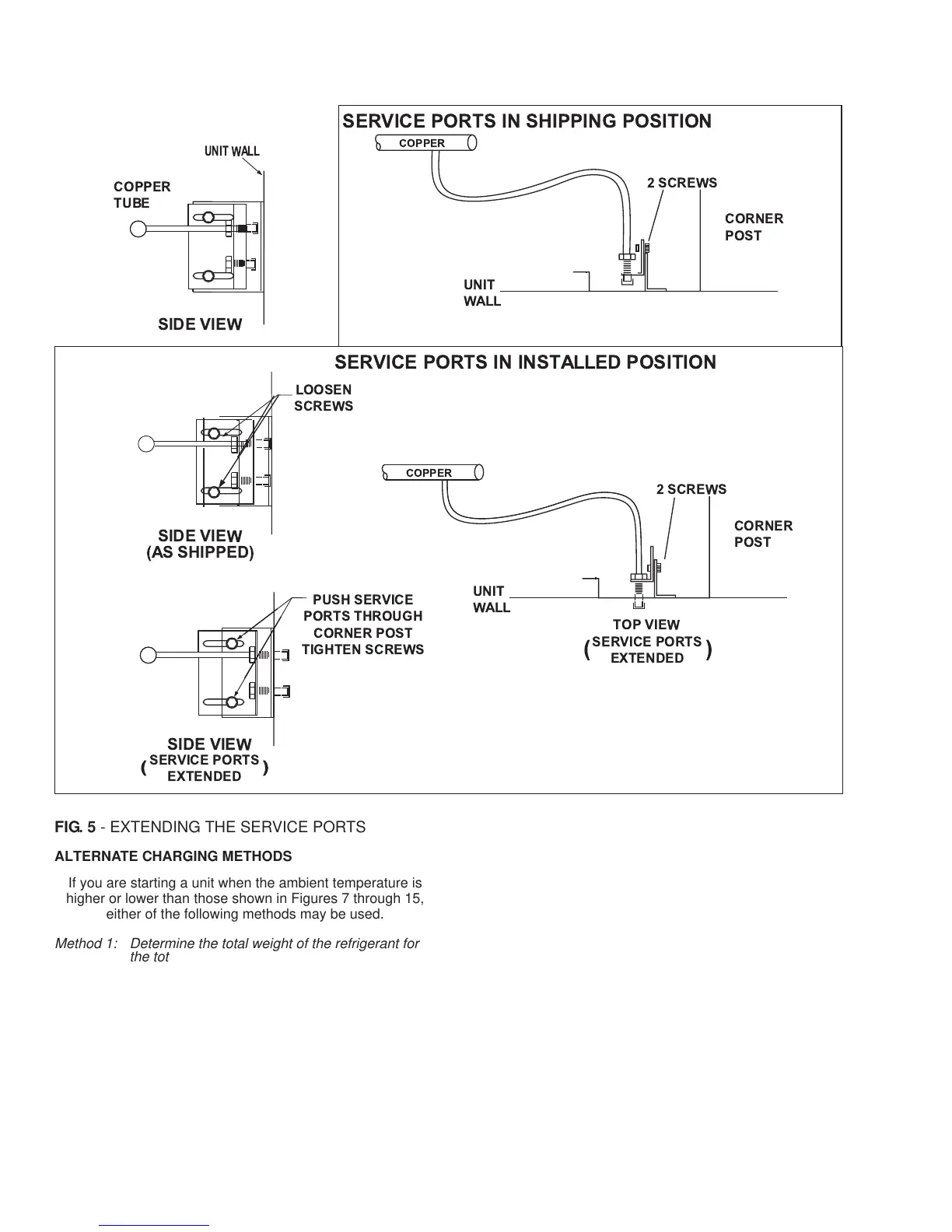
SERVICE PORTS IN SHIPPING POSITION
UNIT WALL
SIDE VIEW
COPPER
TUBE
UNIT
WALL
COPPER
2SCREWS
CORNER
POST
TOP VIEW
UNIT
WALL
LOOSEN
SCREWS
SIDE VIEW
(AS SHIPPED)
PUSH SERVICE
PORTS THROU GH
CORNER POST
TIGHTEN SCREWS
SIDE VIEW
SERVICE PORTS
EXTENDED
()
SERVICE PORTS
EXTENDED
()
SERVICE PORTS IN INSTALLED POSITION
FIG. 5 - EXTENDING THE SERVICE PORTS
ALTERNATE CHARGING METHODS
If you are starting a unit when the ambient temperature is
higher or lower than those shown in Figures 7 through 15,
either of the following methods may be used.
Method 1: Determine the total weight of the refrigerant for
the total system by adding the required charge
for the outdoor unit, the indoor unit and the refrig
-
erant lines using information in Tables 2 (Physi
-
cal Data) and 6 (Refrigerant Line Charge).
Using the charging procedures outlined above,
weigh the required amount of refrigerant charge
into the unit.
Method 2:
Install a field supplied moisture indicating sight
glass in the liquid line between the filter-drier and
the evaporator coil.
Using the charging procedure outlined above,
charge refrigerant until the moisture indicating
sight glass is clear. Add approximately 2 extra
pounds of refrigerant to assure a liquid refrigerant
seal at the expansion valve under all operating
conditions. Block the flow of the condenser air, if
necessary, to assure a head pressure of 280 psig
during the charging procedure.
Note: The installer should return to the job to verify the operat
-
ing charge when the ambient temperature is within the
conditions shown in Figures 7 through 15.
 Loading...