270844-YTG-A-0407
2 Unitary Products Group
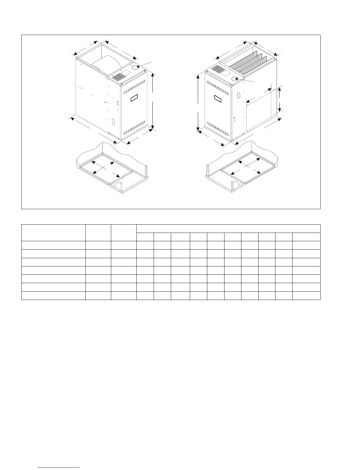
DOWNFLOW
UPFLOW
A
A
B
E
D
BOTTOM VIEW
F
G
29-3/4
29-3/4
C
31-1/2
31-1/2
14
BOTTOM VIEW
H
J
16-1/4
K
K
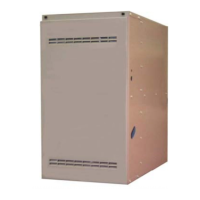
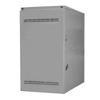
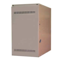
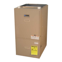
CABINET AND DUCT DIMENSIONS
BTUH (kW)
Input
Nominal
CFM
Cabinet
Size
Cabinet Dimension
A(in.) B(in.) C(in.) D(in.) E(in.) F(in.) G(in.) H(in.) J(in.) K Vent (in.)
G8C05012(MU,MD)B12
1
1200 B 17 1/2 16 1/2 20 3/8 20.0 16 14 3/4 18 3/4 15 1/8 19.0 3
G8C07512(MU,MD)B12
1
1200 B 17 1/2 16 1/2 20 3/8 20.0 16 14 3/4 18 3/4 15 1/8 19.0
4
2
G8C07516(MU,MD)C12
1
1600 C 21 20 20 3/8 20.0 19 1/2 18 1/4 18 3/4 18 5/8 19.0
4
2
G8C10016(MU,MD)C12
1
1600 C 21 20 20 3/8 20.0 19 1/2 18 1/4 18 3/4 18 5/8 19.0
4
2
G8C10020(MU,MD)D11
1
2000 D 24.5 23 1/2 20 3/8 20.0 23 21 3/4 18 3/4 22 1/8 19.0
4
2
G8C12520(MU,MD)D11
1
2000 D 24.5 23 1/2 20 3/8 20.0 23 21 3/4 18 3/4 22 1/8 19.0
5
2
G8C15020UHD11
3
2000 D 24 1/2 23 1/2 20 3/8 20.0 23 21 3/4 18 3/4 22 1/8 19.0
5
2
1. 4-position models may be factory configured as upflow (MU) or downflow (MD).
2. 3-position 150 MBH model available only in upflow/horizontal (UH) configuration.
4. Dimensions “B”, “C”, “D”, and “E” are with duct flanges turned up. “F”, “G”, “H”, & “J” are with flanges flat.
3. All models are supplied with 3” (7.62 cm) vent connections. An installer supplied transition to 4” (10.16 cm) or 5” (12.7 cm) must be used where necessary.
 Loading...