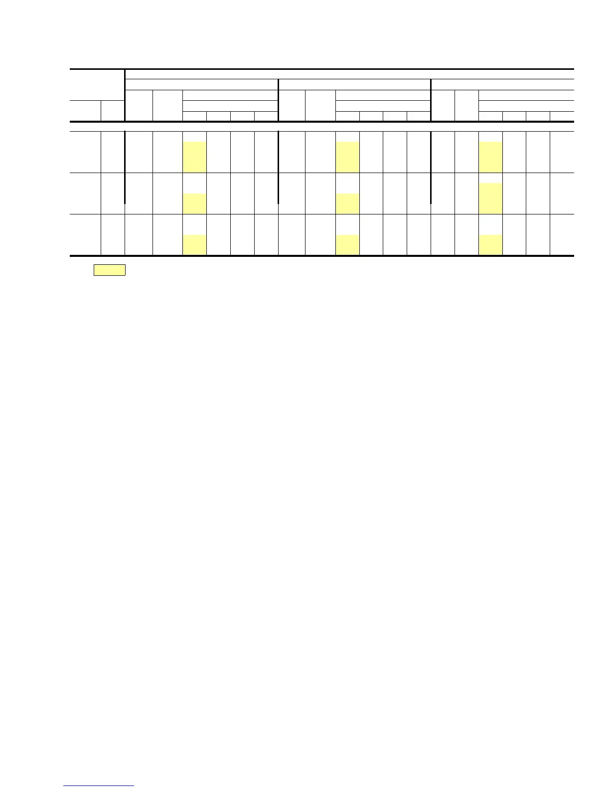
All Sensible Capacity
Air On
Cooling
Coil
Temperature of Air on Condenser
95
°F 105°F 115°F
Total
Cap.,
MBH
Power
Input,
KW
Sensible Capacity, MBH
Total
Cap.,
MBH
Power
Input,
KW
Sensible Capacity, MBH
Total
Cap.,
MBH
Power
Input,
KW
Sensible Capacity, MBH
CFM
WB
°F
Entering Dry Bulb,
°F Entering Dry Bulb, °F Entering Dry Bulb,°F
86 80 74 68 86 80 74 68 86 80 74 68
H1CE150/K1EU180
6250
72 163 13.7 135 99 63 - 156 15.1 132 96 60 - 149 16.8 129 94 58 -
67 157 13.5 157 130 94 57 151 15.0 151 127 91 55 145 16.7 145 124 89 52
62 157 13.5 157 147 125 89 151 15.0 151 141 122 87 144 16.7 144 135 119 84
57 156 13.5 156 147 137 119 150 15.0 150 141 132 116 144 16.7 144 135 126 113
5000
72 160 13.6 12. 90 60 - 153 15.0 118 88 57 - 145 16.7 115 85 55 -
67 150 13.3 144 117 87 56 144 14.8 141 114 84 53 138 16.5 138 111 81 51
62 149 13.3 149 139 113 83 143 14.8 143 134 110 80 137 16.5 137 129 107 77
57 148 13.3 148 139 131 108 143 14.8 143 134 125 105 137 16.5 137 129 120 102
3750
72 155 13.4 104 81 57 - 148 14.9 102 79 54 - 141 16.6 100 76 52 -
67 143 13.2 125 102 79 54 137 14.6 122 99 76 52 131 16.3 119 97 73 49
62 137 13.0 137 122 99 76 132 14.5 132 119 96 73 127 16.2 127 116 93 70
57 137 13.0 137 129 118 96 132 14.5 132 124 115 93 127 16.2 127 119 111 90
NOTE: These capacities are gross ratings. For net capacities, determine the KW requirement of the supply air blower motor per the published BLOWER PERFORMANCE data. Convert
KW to MBH per the following equation and deduct this equivalent heat from the gross cooling ratings.
The KW input ratings listed above include the compressor and condenser fan motor(s).
UNIT OPERATION - 7-1/2, 10 & 12-1/2 TON
When the external control calls for cooling at terminal Y1:
1. The system controller (SC) is energized. The system con-
troller starts the tandem compressors and enables the
condenser fans by energizing contactor 1M (and 2M on
the 10 and 12-1/2 ton, 208/230 volt models).
The single condenser fan is energized with the compres-
sors on the 7-1/2 ton models.
Condenser fan motor #1 is energized with the compres-
sors on the 10 and 12-1/2 ton models while fan #2 is en-
abled with compressor operation. Fan motor #2 operation
is controlled through the Ambient Temperature Switch
(ATS) which will de-energize the motor when the ambient
temperature falls below 70
°F.
2. Safety Lockout: The system controller (SC) has a lockout
circuit to prevent compressor short-cycling on a safety
control with automatic reset. If the high or low refrigerant
pressure switches (HP or LP) open, the SC will enter
lockout mode.
SC provides a 90 second bypass of the low pressure switch
LP to prevent nuisance lockouts during unit start-up.
A malfunction light (24V, 2 A max. resistive load) can be en-
ergized through SC, by connecting the light between termi-
nals X and B on TB1.
NOTE: To reset the unit after a lockout:
A. Turn the system switch on the thermostat to the ‘‘OFF’’
position and back to the ‘‘COOL’’ position.
OR
B. Increase the set point of the room thermostat above the
temperature in the conditioned space and returning it to its
original setting.
If the unit continues to be shut down by one of its safety controls,
a service man should be called to determine the cause of the
problem. Repeated resetting of the lockout circuit may damage
the unit.
SYSTEM COOLING CAPACITIES AND POWER REQUIREMENTS
SEQUENCE OF OPERATION
550.23-TG1Y
Unitary Products Group 5
 Loading...