292424-XIM-A-0307
Unitary Products Group 7
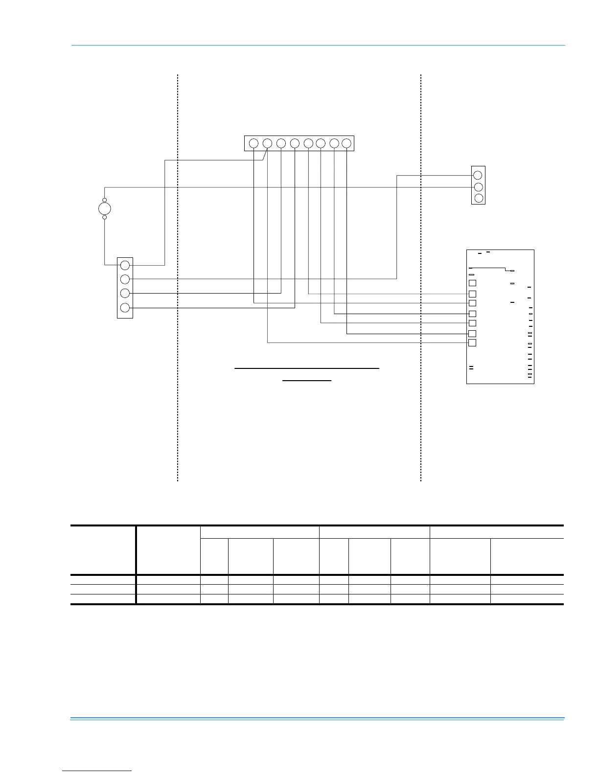
FIGURE 1 - TYPICAL FIELD WIRING DIAGRAM
R C W1 Y1 Y2 G
C
G
W1
W2
G1
Sol
POS1
LIMIT
SD
C
FAN OVER
LOW AMB
SD
SD
Y1
Y2
C
LPS1
HPS1
C2
LPS2
HPS2
Y1-ECON
Y1-OUT
C1
R
24/120 VAC
OUTPUTS
R
PO 1
PO 2
THERMOSTAT
OUTDOOR
INDOOR
SPLIT SYSTEM CONNECTION
DIAGRAM
W2 X
X
G
Sol
TB3
TABLE 4: ELECTRICAL DATA
Model
Unit Power
Supply
Compressor Condenser Fan Motor Unit
Qty.
RLA
1
LRA
1
Qty. Hp/kW FLA
Min. Circuit
Ampacity
(Amps)
Max. Fuse
2
/
Breaker Size
3
(Amps)
H3CE150A50 380/415-3-50 2 13.9 94 2 1/.75 2.2/2.0 35.7 45
H4CE180A50 380/415-3-50 2 19.2 110 / 118 2 1/.75 4.0/3.6 51.2 70
H3CE240A50 380/415-3-50 2 18.3 /24.3 127 / 158 2 1/.75 4.0/3.6 55.0 80
1.
RLA and LRA values are for one (1) compressor.
2.
Dual element, time delay type fuses or HACR circuit breakers.
3.
HACR type per NEC.
 Loading...