 Loading...
Do you have a question about the York MV and is the answer not in the manual?
| Brand | York |
|---|---|
| Model | MV |
| Category | Air Conditioner |
| Language | English |
Modular variable speed air handlers for split system cooling and heat pump applications.
System flexibility, blower, coil, and electric heater details for versatile application.
Available accessories and operational limitations including wiring and voltage requirements.
Table detailing physical dimensions (A, B, C, D, E) and wiring knockouts (J, K).
Cooling capacity data for various coil models at different temperature/pressure points.
Physical specifications for blower units including dimensions and motor details.
Details on coil models, application, face area, rows, tube geometry, and operating weight.
Electrical data for single-phase units including total heat output and staging.
Electrical data for three-phase units including total heat output and staging.
Wiring details for single-phase supply, including heater amps, min. circuit ampacity, and wire size.
Wiring details for three-phase supply, including heater amps, min. circuit ampacity, and wire size.
Data for multi-source supply, detailing ampacity and wire size for different heaters.
Electrical data for cooling-only units, including motor amps and minimum circuit ampacity.
Diagrams showing typical wiring for units without electric heat and with electric heat.
Description of filter rack accessories and their dimensions for various models.
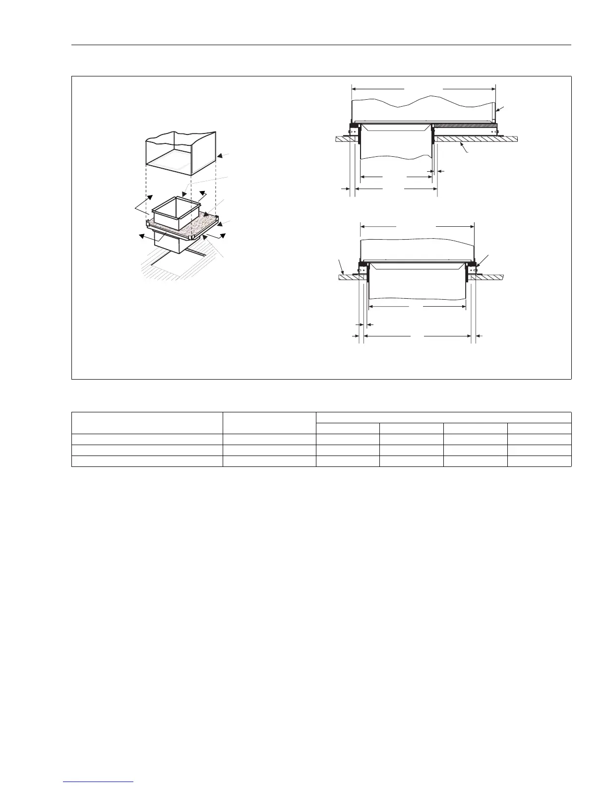
Requirement for floor base accessories when installing units with electric heat in downflow.
Table showing dimensions for combustible floor base accessories based on unit models.
Cooling airflow data for various air handler models, including CFM and jumper settings.
Heating airflow data for various air handler models, including CFM and jumper settings.
Factors for adjusting rated CFM based on actual airflow percentages.
Control wiring diagrams for AC cooling-only, electric heat, and HP systems.