505428-YTG-V-0417
Johnson Controls Unitary Products 117
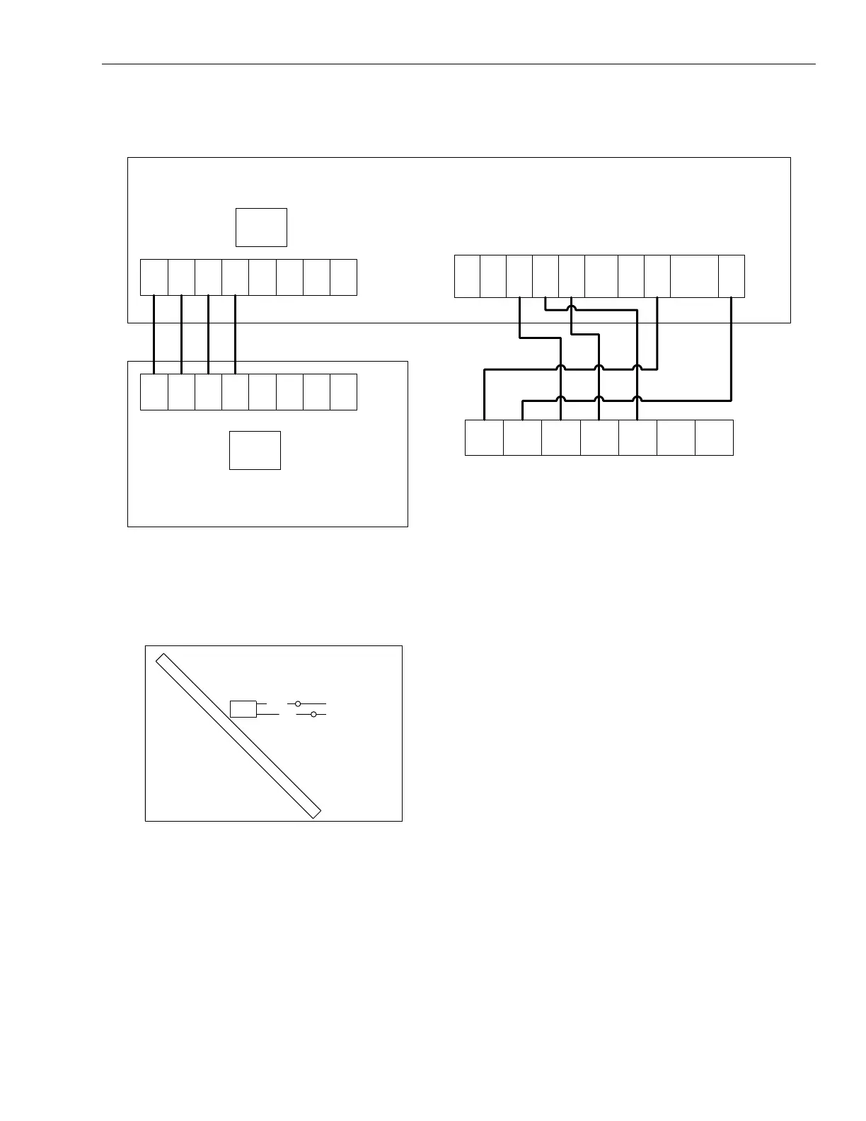
Typical Field Wiring Diagram - NC300 Evaporator Unit with YC300 Condenser Unit
NOTE: On non NC/ Evaporator models, isolation relays must
be installed to avoid overloading on 75 VA
transformers on the condensing unit.
Typical NC300 Liquid Line Solenoid Wiring
W1 W2 Y1 G Y2 0CC CX R SD-24
SE CONTROL BOARD
THERMOSTAT CONNECTIONS
TB2
TB1
CONDENSER CONTROL BOX
EVAPORATOR CONTROL BOX
THERMOSTAT
TWO STAGE COOL
R C Y1 Y2 G W1 W2
C S1 S2 G1 G2 66 60 X
C S1 S2 G1 G2 66 60 X
219 / Y
218 / BR
1LLS
VALVE SYS 2
BLK
BLK
C O I L