679948-YTG-A-0111
Unitary Products Group 17
ACCESSORIES
• ELECTRIC HEATER - Add 14-1/4” to unit height when using 10,
16, 26, or 36 KW heater
• SUPPLY AIR PLENUM - Add 27” to unit height when used.
• BASE - Add 24” to unit height when used.
• HOT WATER OR STEAM COIL - Add 6” to unit depth when used.
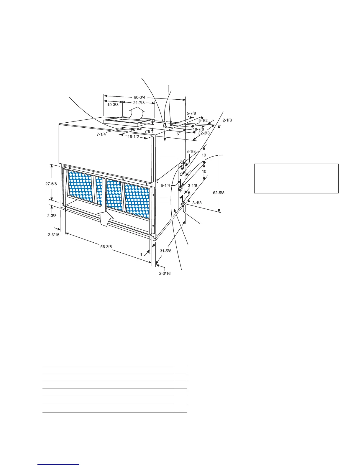
FIGURE 9 - UNIT DIMENSIONS - NE180
BLOWER MOTOR AND DRIVE ACCESS PANEL
(Always on the wiring connection side of unit)
Located on opposite side ONLY when the blower
section has been rotated 180° from position shown.
1-23/32” KNOCKOUT
Remove only when Electric
Heat Accessory is used.
7/8” KNOCKOUT FOR POWER WIRING
Do not remove this knockout when the unit is equipped with an Electric
Heat Accessory. Refer to detail of the Heater Accessory for power
wiring access opening.
7/8” KNOCKOUT FOR
CONTROL WIRING
ALTERNATE
2-5/8” KNOCKOUT*
2-5/8”
KNOCK-
OUT FOR
SUCTION
CONN.*
1-1/4” KNOCKOUT
FOR 7/8” OD DRAIN
CONNECTION*
(Must be trapped)
FILTER ACCESS PANEL
Filters can be removed
through either side of
the unit.
1-1/4” KNOCKOUT FOR
LIQUID CONNECTION*
COIL
SECT
BLOWER
SECTION
*Refer to INSTALLING REFRIGERANT MAINS in installation instruction
when piping through the opposite side of the unit.
AIR
IN
AIR
OUT
All dimensions are in inches. They are
subject to change without notice. Certi-
field dimensions will be provided upon
request.
TABLE 24: UNIT CLEARANCES - NE180
MINIMUM CLEARANCES 180
Side Air with RETURN AIR opening 24”
Side with SUPPLY AIR opening
1
24”
Side with PIPING CONNECTIONS 24”
Side opposite PIPING CONNECTIONS
2
24”
Bottom
3
-
1. Overall dimension of the unit will vary if an electric
heater, a supply air plenum or a base is used.
2. If the coil has to be removed, this dimension is required
to loosen screws that secure the coil to the unit frame.
This dimension will also be required for blower motor
access if the piping connections are made on the oppo-
site side of the unit.
3. Allow enough clearance to trap the condensate drain
lines.
All dimensions are in inches. They are
subject to change without notice. Certi-
fied dimensions will be provided upon
request.
 Loading...