035-17477-001 Rev. A (801)
24 Unitary Products Group
CONDENSATE PIPING
The condensate drain connection is packed in the furnace for
field installation. It consists of a formed hose with a 1/2” NPT
male connection. A 1/2” FM x 3/4” PVC slip coupling is pro-
vided.
This drain hose may be installed to allow left or right side con-
densate drain connection, refer to Figures 33 and 34. Cut the
hose to allow for proper fit for left or right exit.
To install the drain hose assembly, remove the 7/8” knockout
in the side panel. Remove the conduit nut from the 1/2” male
fitting. Push the male fitting through the hole and reinstall the
nut. The use of the 3/4” PVC coupling is optional.
CONVERSION FOR HORIZONTAL APPLICATIONS
(DOWNFLOW MODELS ONLY)
Remove the condensate trap and its mounting bracket from
the unit side panel. Remove all drain hoses.
Reinstall the trap/bracket on the side panel which will be on
the bottom when the unit is located horizontally. Use the orig-
inal mounting screws.
Refer to Figure 35 for hose locations and Table 8 for hose cut
lengths. All hoses are identified as shown in Figure 35.
For horizontal left airflow (inducer and vent low) or horizontal
right airflow (inducer and vent high), install condensate drain
hoses as follows:
RIGHT AIRFLOW (Inducer High) - Three hoses are required.
Hoses are supplied with furnace. Refer to Figure 35 and
Table 8 for application.
LEFT AIRFLOW (Inducer Low) - Two hoses are required.
Inducer outlet to trap is supplied. Condensate pan to trap
must be field supplied using 5/8” I.D. hose material. Refer to
Figure 35 and Table 8, for hose placement and sizing..
Drain Connection:
The following steps apply to all models.
For horizontal application, also follow the procedure for relo-
cating the trap assembly and installing drain hoses.
1. It is recommended that either 1/2” or 3/4” PVC or equiva-
lent pipe be field installed as drain pipe. The condensate
piping may be tied together with the air conditioning con-
densate drain if the air conditioning condensate drain
line is trapped upstream of the tie-in and the combined
drains are constructed of the same material.
2. All pipe joints must be cleaned, de-burred and cemented
using PVC primer and cement.
3. The furnace contains an internal trap. Therefore, no
external trap should be used.
4. If a condensate pump is used, it must be suitable for use
with acidic water.
5. Where required, a field-supplied neutralizer can be
installed in the drain line, external to the furnace.
NOTE:
The condensate drain from the furnace may be con-
nected in common with the drain from an air conditioning coil
if allowed by local code. Follow the instructions with the coil
for trapping the drain.
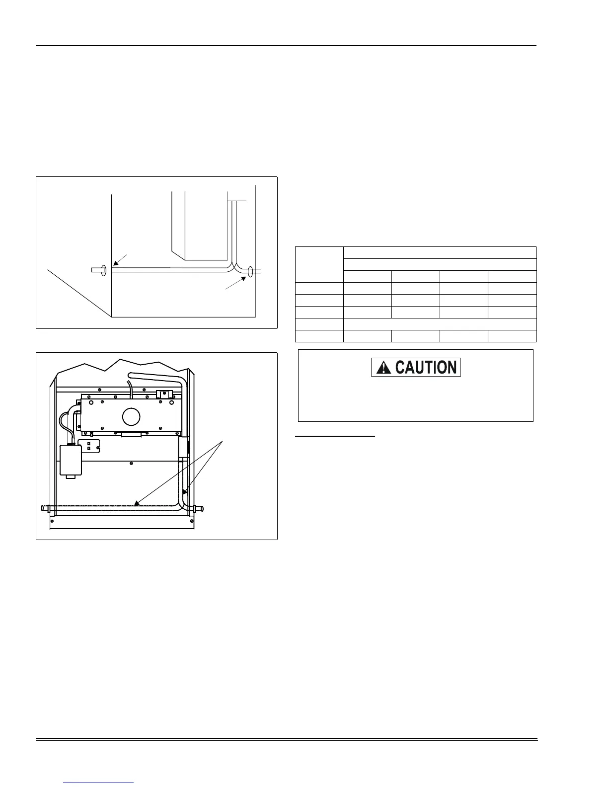
FIGURE 33 :
Condensate Piping - Upflow Models
FIGURE 34 :
Downflow/Horizontal Models
LH DRAIN
RH DRAIN
CONDENSATE
TRAP TUBING
Table 8:
HORIZONTAL CONDENSATE DRAIN HOSE SIZES -
MODELS P*DH / FG9-DH / G9T-DH
DIMEN.
CABINET SIZE (IN.)
RIGHT AIRFLOW (INDUCER HIGH)
14-1/2 17-1/2 21 24-1/2
A 4-1/2 4-3/4 3-1/2 5-1/4
B 7-1/2 10-1/2 14 17-1/2
C 13-1/2 16-1/2 20 23-1/2
LEFT AIRFLOW (INDUCER LOW)
D 3-3/8 3-1/4 3-1/4 3-1/4
Plug all unused condensate trap, condensate pan
and inducer drain connection points using plugs
provided.
 Loading...