035-17477-001 Rev. A (801)
Unitary Products Group 25
SAFETY CONTROLS
Control Circuit Fuse:
A 3 amp. fuse is provided to protect
the 24 volt transformer from overload caused by control cir-
cuit wiring errors. This is an ATO 3, automotive type fuse and
is located on the ignition control module.
Blower Door Safety Switch:
This unit is equipped with an
electrical interlock switch mounted in the blower compart-
ment. This switch interrupts all power at the unit when the
panel covering the blower compartment is removed.
Electrical supply to this unit is dependent upon the panel that
covers the blower compartment being in place and properly
positioned.
Rollout Switch Controls:
These controls are mounted on
the burner box assembly. If the temperature in the burner
compartment exceeds its set point, the igniter control and the
gas valve are de-energized. The operation of this control indi-
cates a malfunction in the combustion air blower, heat
exchanger or a blocked vent pipe connection. Corrective
action is required. This is a manual reset control and must be
reset before operation can continue.
Pressure Switches:
This furnace is supplied with pressure
switches which monitor the flow through the combustion air/
vent piping system. These switches de-energize the ignition
control module and the gas valve if any of the following condi-
tions are present. Refer to Figure 36 for tubing connections.
1. Blockage of combustion air piping or terminal. (1LP)
2. Blockage of vent piping or terminal (1LP).
3. Failure of combustion air blower motor (1LP).
4. Blockage of condensate drain piping:
• Upflow units (1LP)
• Downflow/Horizontal Units
• Downflow (1LP)
• Horizontal Left (1LP)
• Horizontal Right (2LP).
Limit Controls:
There is high temperature limit control
located on the furnace vestibule panel near the gas valve.
This is a automatic reset control that provide over tempera-
ture protection due to reduced airflow, such as a dirty filter.
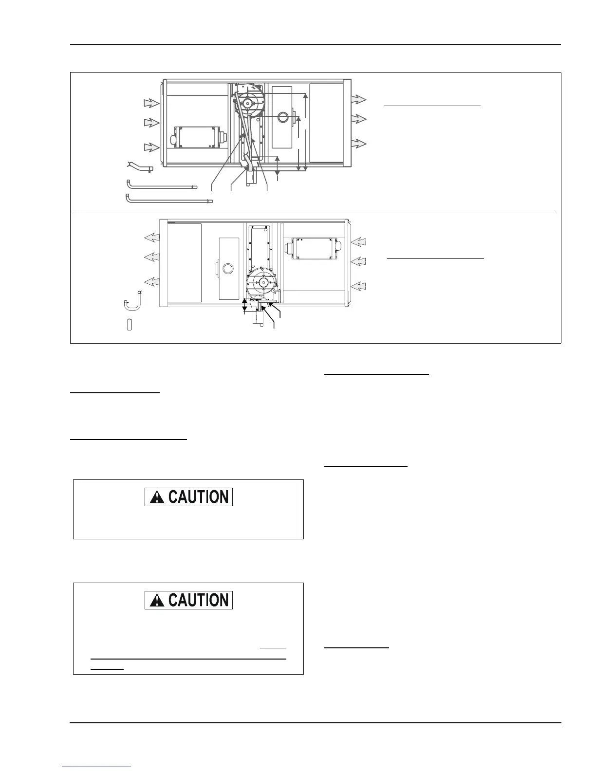
FIGURE 35 :
Horizontal Application Condensate Drain Connection (Models P*DH / FG9-DH / G9T-DH)
RIGHT AIRFLOW
(INDUCER HIGH)
LEFT AIRFLOW
(INDUCER HIGH)
1. CONDENSATE PAN TO TRAP “A” DIMENSIONS.
2. INDUCER BOTTOM TO TRAP “B” DIMENSIONS.
3. INDUCER OUTLET TO TRAP “C” DIMENSIONS.
1. INDUCER OUTLET TO TRAP USE AS PROVIDED.
5. CONDENSATE PAN TO TRAP “D” DIMENSIONS.
3
1
2
A
D
5
4
B
C
HOSE IDENTIFIER NUMBERS:
HOSE IDENTIFIER NUMBERS:
Blower and burner must never be operated without
the blower panel in place.
Main power to the unit must still be interrupted at
the main power disconnect switch before any ser-
vice or repair work is to be done to the unit. Do not
rely upon the interlock switch as a main power dis-
connect.
 Loading...