035-17477-001 Rev. A (801)
30 Unitary Products Group
ADJUSTMENT OF TEMPERATURE RISE
The temperature rise, or temperature difference between the
return air and the heated air from the furnace, must be within
the range shown on the furnace rating plate and within the
application limitations are shown in Tables 1 or 2. After the
temperature rise has been determined, the airflow (cfm) can
be calculated.
After about 20 minutes of operation, determine the furnace
temperature rise. Take readings of both the return air and the
heated air in the ducts, about six feet from the furnace where
they will not be affected by radiant heat.
Increase the blower speed to decrease the temperature rise;
decrease the blower speed to increase the rise.
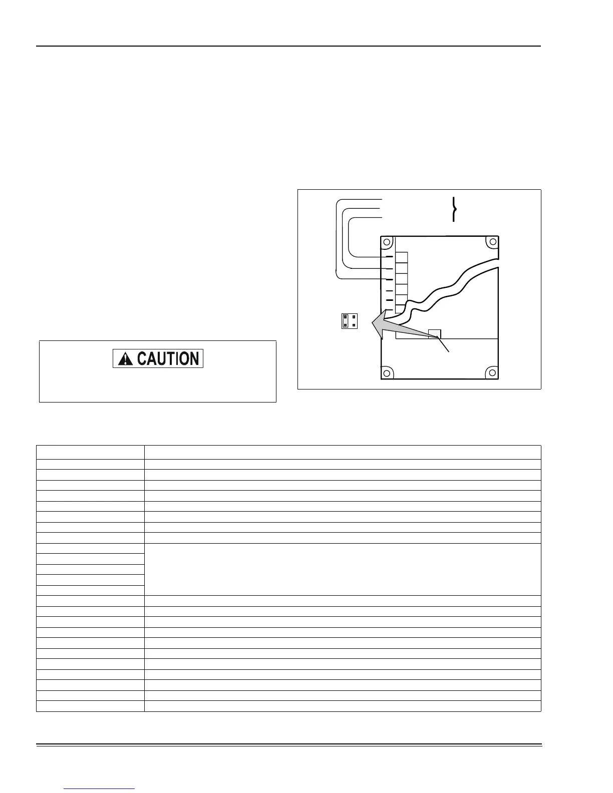
All direct-drive blowers have multi-speed motors. The blower
motor speed taps are located in the control box in the blower
compartment. Refer to Figure 40, and the unit wiring label to
change the blower speed.
You may select a heating speed and a cooling speed. They
may be the same speed or a different speed.
To use the same speed tap for heating and cooling, the heat
terminal and cool terminal must be connected using a jumper
wire and connected to the desired motor lead. Place all
unused motor leads on Park terminals. Two are provided.
ADJUSTMENT OF FAN-OFF CONTROL SETTINGS
This furnace is equipped with a time-on/time-off heating fan
control. The fan on delay is fixed at 30 seconds. The fan off
delay is field adjustable from 60 to 180 seconds. The fan off
delay is factory set to 120 seconds.
The fan-off setting must be long enough to adequately cool
the furnace, but not so long that cold air is blown into the
heated space.
The fan-off timing may be adjusted by positioning the jumper
located on the control board. Refer to Figure 40.
FURNACE ACCESSORIES
* Substitute 2 for York brands and 6 for non York brands.
Do not energize more than one motor speed at a
time or damage to the motor will result.
FIGURE 40 :
Typical Heat/Cool Speed Tap
Connections
COOL
BLK - HIGH SPEED
BLU - MEDIUM SPEED
RED - LOW SPEED
BLK
BLU
RED
MOTOR LEADS
FAN OFF
ADJUSTMENT
SWITCHES
60
90
120
180
HEAT
PARK
PARK
LINE
XM
ELECTRICAL
*ET03700324 Single Stage Thermostat, One-Stage Heat/One-Stage Cool, Non-Programmable
*ET03700124 Deluxe Single Stage Theromstat, One Stage Heat /One Stage Cool, Programmable
2TH13700424 Single Stage Thermostat, One Stage Heat, Round - 2TB17700424 Heat/Cool Subbase
6TH13701024 Single Stage Thermostat, One Stage Heat, Round - 2TB17700424 Heat/Cool Subbase
2TC03700124 Twinning Control
NON-ELECTRICAL
1NP0347 Propane (LP) Conversion Kit
1NP0349 Propane (LP) Conversion Kit
1PS0306
High Altitude Pressure Switch (See Form 650.75-N2.1V for proper application)
1PS0307
1PS0308
1PS0309
1PS0310
1SR0302BK External Side Filter Rack (6-Pack)
1BR0314 External Bottom or Horizontal Filter Rack - Cabinet “A”
1BR0317 External Bottom or Horizontal Filter Rack - Cabinet “B”
1BR0321 External Bottom or Horizontal Filter Rack - Cabinet “C”
1BR0324 External Bottom or Horizontal Filter Rack - Cabinet “D”
1CT0302 Concentric Vent Termination - 2” Vent Pipe
1CT0303 Concentric Vent Termination - 3” Vent Pipe
1CB0314 Combustible Floor Base - Cabinet “A”
1CB0317 Combustible Floor Base - Cabinet “B”
1CB0321 Combustible Floor Base - Cabinet “C”
1CB0324 Combustible Floor Base - Cabinet “D”
 Loading...