035-14370-000 650.75-N4U
Unitary Products Group 13
NOTE
:
An accessible manual shutoff valve must be installed
upstream of the furnace gas controls and within 6 feet of the
furnace.
The installation of a ground joint union and drip leg are
required. (Refer to Figure 10.) Maximum and minimum sup-
ply gas pressures are shown below.
NOTE
:
A 1/8” NPT plug is included in the inlet side of the gas
valve for measuring incoming gas pressure.
The furnace must be isolated from the gas supply piping sys-
tem by closing its individual external manual shutoff valve
during any pressure testing of the gas supply piping system
at pressures equal to or less than 1/2 psig (3.48 kPa).
The furnace and its individual shutoff valve must be discon-
nected from the gas supply piping system during any pres-
sure testing of that system at test pressures in excess of 1/2
psig (3.48 kPa).
ELECTRICAL POWER CONNECTION
Field wiring to the unit must conform to and be grounded in
accordance with the provisions of the National Electrical
Code ANSI/NFPA No. 70-latest edition, Canadian Electric
Code C22.1 Part 1 - (latest edition) and/or local codes. Elec-
tric wires which are field installed shall conform with the tem-
perature limitation for 63°F/35°C rise wire when installed in
accordance with instructions. Specific electrical data is given
for the furnace on its rating plate and in Refer to Table 1 on
page 6.
Provide a power supply separate from all other circuits. Install
overcurrent protection and disconnect switch per local/
national electrical codes. The switch should be close to the
unit for convenience in servicing. With the disconnect switch
in the OFF position, check all wiring against the unit wiring
label. Also, see the wiring diagram in this instruction.
NOTE
:
The furnace’s control system depends on correct
polarity of the power supply and a proper ground connection.
“FURNACE CONTROL DIAGNOSTICS" Section on pa
e37
for symptoms of reversed power supply polarity.
Connect the power supply as shown on the unit wiring label
on the inside of the blower compartment door and Figures 11
& 12. The black furnace lead must be connected to the L1
(hot) wire from the power supply. The white furnace lead
must be connected to neutral. Also, the green equipment
ground wire must be connected to the power supply ground.
Remove the screws retaining the wiring box cover. Route the
power wiring through the unit top panel with a conduit con-
INLET GAS PRESSURE RANGE
Natural Gas Propane (LP)
Minimum 4.5 In. W.C. 11 In. W.C.
Maximum 13.8 In. W.C. 13.8 In. W.C.
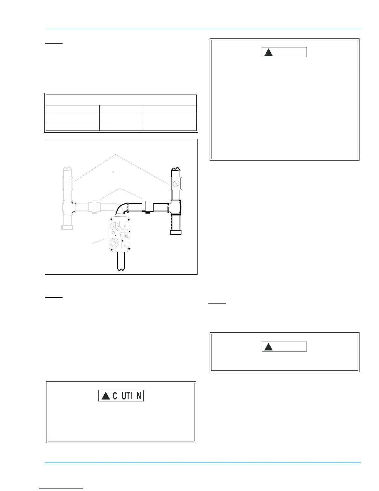
FIGURE 10 : GAS PIPING
Never apply a pipe wrench to the body of the com-
bination automatic gas valve. A wrench must be
placed on the projection or wrench boss of the
valve when installing piping to it.
GAS VALVE
DROP LEG
GROUND JOINT UNION
M A Y B E IN STALLED
IN S ID E O R O U T S ID E U N IT
TO G A S
SUPPLY
EXTERNAL MANUAL
SH U TO FF VALVE
TO G A S
SUPPLY
DROP LE
Compounds used on threaded joints of gas piping
must be resistant to the action of liquefied petro-
leum gases. After connections are made, leak-test
all pipe connections.
After all gas piping connections are completed,
leak test all joints, fittings and furnace connections
with rich soap and water solution, commercially
available bubble type leak detection fluid, or other
approved means.
Do not use an open flame or other source of igni-
tion for leak testing.
Use copper conductors only.
 Loading...