035-14370-000 650.75-N4U
Unitary Products Group 29
EXAMPLE - CHECKING GAS INPUT
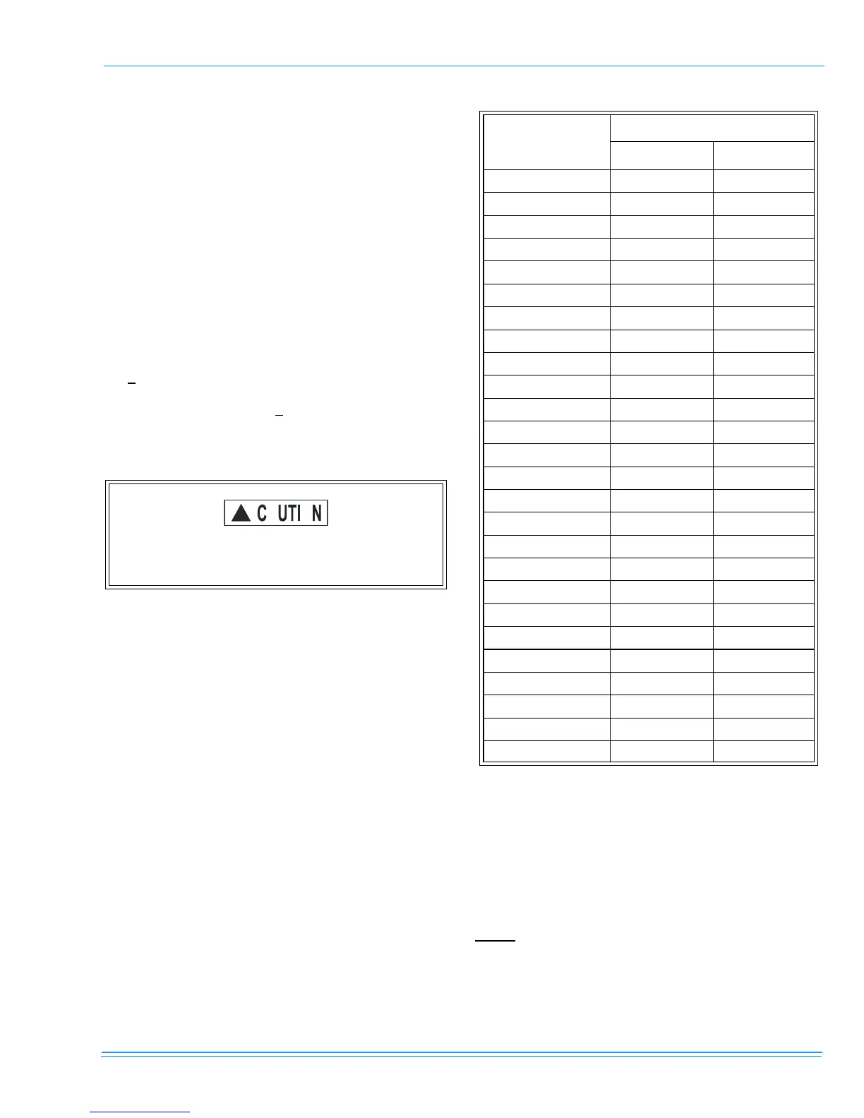
It is found by measurement that it takes 26 seconds for the
hand on the 1 cubic foot dial to make a revolution with only a
120,000 Btuh furnace running. Using this information, locate
26 seconds in the first column of Table 9, “
as rate (cubic feet
per hour),” on page 29. Read across to the column headed
1
cubic foot
where you will see that 138 cubic feet of gas per
hour are consumed by the furnace at that rate.
With the barometer at 28.9" and a 70° F temperature, the cor-
rection factor will be.945. If the local gas heating value is 935
BTU per cubic foot the calculations will be as follows:
138 cu. ft/hrx.945 correction factor x 935 BTU/cu. ft. =
121,933 BTU/Hr.
The calculated firing rate of 121,933 BTU per hour is within
the
+
2% tolerance of our nominal 120,000 furnace..
If the actual input is not within
+
2% of the furnace rating, with
allowance being made for the permissible range of the regu-
lator setting (0.3 inches W.C.), replace the orifice spuds with
spud of the proper size.
ADJUSTMENT OF MANIFOLD GAS PRESSURE
Manifold gas pressure may be measured by two different pro-
cedures. It may be measured with the burner box cover in
place or it may be measured with the burner box cover
removed. Follow the appropriate section, 2a or 2b in the
instructions below.
1. Turn
as off at main
as valve. Revove 1/8” Allen socket
head pipe plu
from the manifold end of the main
as
valve. Install the proper manometer tube adapter into
this openin
.
2. Read the inlet
as pressure usin
either of the two meth-
ods below.
a.
Reading the gas pressure with the burner box
cover in place
- Disconnect the pressure reference
hose from the right side of the burner box. Using a
tee fitting and a short piece of hose, connect the
negative side of the manometer to the burner box
pressure reference port. Connect the positive side
of the manometer to the adapter previously installed
in the gas valve Refer to Figures 39 and 40 on
page 31.
b.
Reading the gas pressure with the burner box
cover removed
- Remove the screws securing the
burner box front cover plate. Remove the cover. It is
gasketed and may stick in place. Connect the posi-
tive side of the manometer to the adapter previously
installed in the gas valve as shown in Refer to Fig-
ures 39 and 40 on page 31. There will be no second
connection to the manometer as it will reference
atmospheric pressure.
NOTE:
The screw-off cap for the pressure regulator must be
removed entirely to gain access to the adjustment screw.
Loosening or tightening the cap does not adjust the flow of
gas.
Be sure to relight any gas appliance that were
turned off at the start of this input check.
TABLE 9 : GAS RATE (CUBIC FEET PER HOUR)
SECONDS
FOR
ONE
REVOLUTION
SIZE
OF
TEST
DIAL
1/2
CUBIC
FOOT
1
CUBIC
FOOT
10 180 360
12 150 300
14 129 257
16 113 225
18 100 200
20 90 180
22 82 164
24 75 150
26 69 138
28 64 129
30 60 120
32 56 113
34 53 106
36 50 100
38 47 95
40 45 90
42 43 86
44 41 82
46 39 78
48 37 75
50 36 72
52 35 69
54 34 67
56 32 64
58 31 62
60 30 60
 Loading...