JOHNSON CONTROLS
194
FORM 150.67-NM1
ISSUE DATE: 4/28/2017
SECTION 8 – UNIT OPERATION
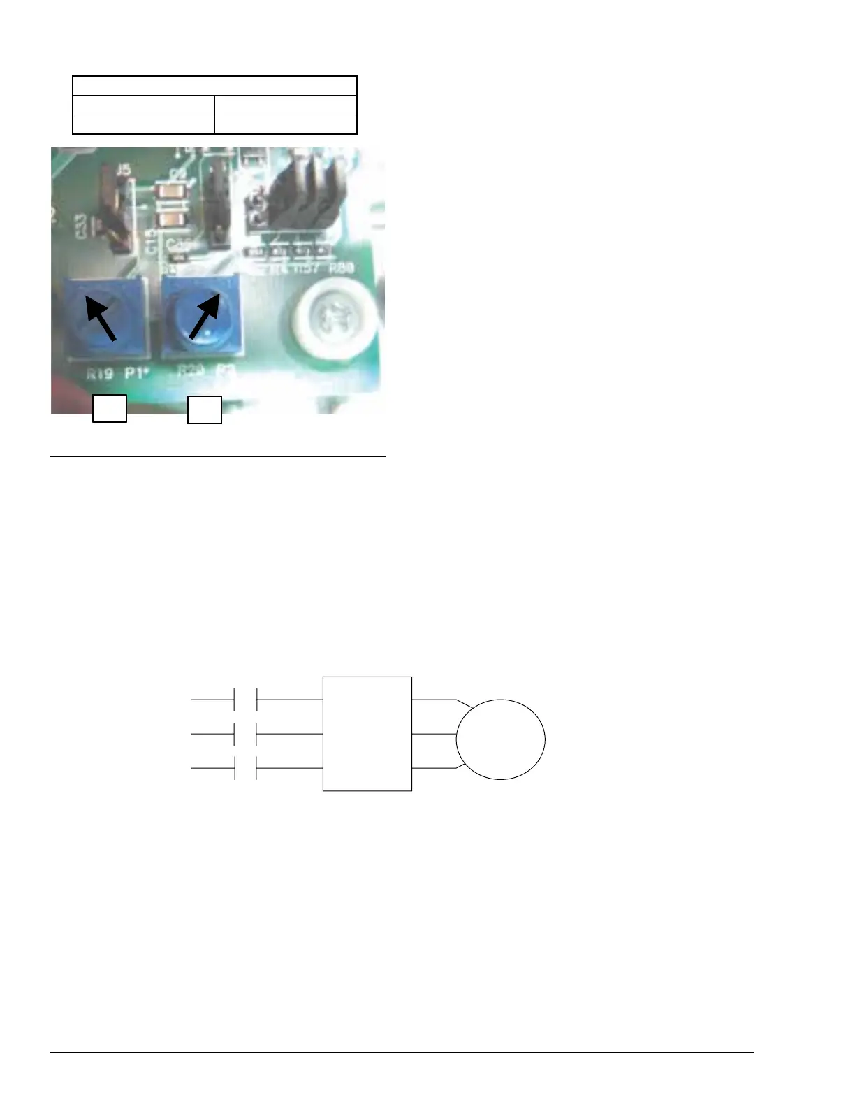
Potentiometer settings are also preset at the factory.
The potentiometers should be in the positions shown in
Figure 51. The pots do not have numerical settings and
are set according to the arrow positions indicated. DO
NOT change the potentiometer settings unless they do
P1
P1
POTENTIOMETER SETTINGS
P1 P2
292 PSI 32 PSI
FIGURE 51 - POTENTIOMETER SETTINGS
LD11300A
not match the positioning of the potentiometers shown
in Figure 51. The position of the potentiometers are as
follows:
• P1 should be full CW (292 PSIG)
• P2 should be full CCW (32 PSIG).
Modifying these settings may cause damage to the
chiller or control problems.
The P1 pot sets the setpoint which is the top end of the
control range. This setting is the discharge pressure at
which the fan will be operating at full speed. The P2
pot sets the range. This is the range of pressure where
the VSD modulates the fan speed from 0 RPM to full
speed. The range is subtracted from the setpoint to cal-
culate the 0 RPM pressure.
Wiring
VFD wiring is simple and requires only 3-phase power
in, 3-phase power out, and a 2-wire signal from the
transducer. No start, stop, or other alternate power re-
quirements are needed to run the VFD. Figure’s 52 and
51 show the power and control wiring schematically
as well as the actual connections. The VFD controlled
fan will operate whenever the liquid line solenoid on
the respective system is energized.
FIGURE 52 - INVERTER POWER WIRING SCHEMATIC
150A L1 T1 150
151A L2 T2 151
152A L3 T3 152
CONDENSER
FAN NO. 1
SPEED
CONTR.
7M
LD11301A
 Loading...


