85
JOHNSON CONTROLS
FORM 150.68-ICOM1
ISSUE DATE: 10/15/2020
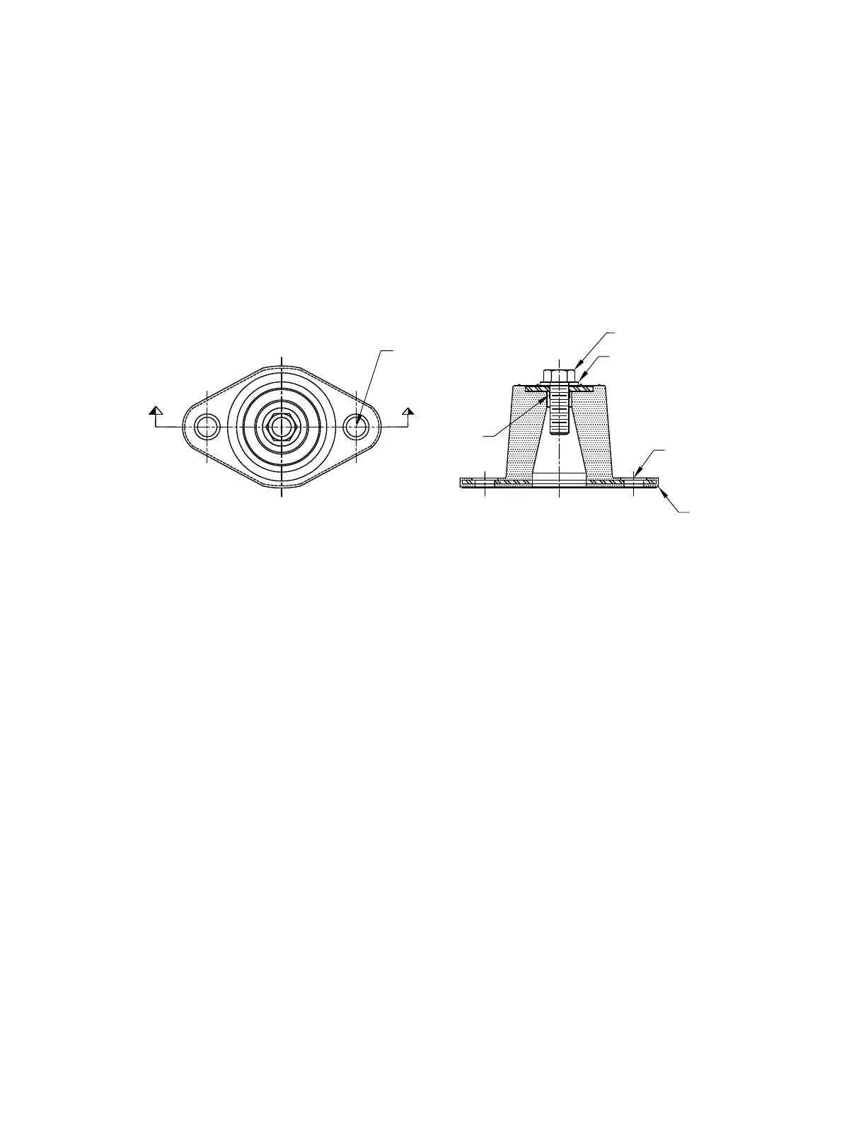
DURULENE ISOLATORS INSTALLATION
LD13762B
D
D
TOP BOLT
C
L
SECTION D-D
TOP WASHER
("A")
("B")
C
L
("C")
("B")
1. Read instructions in their entirety before beginning
installation.
2. Isolators are shipped fully assembled and are to be
positioned in accordance with the submittal draw-
ings or as otherwise recommended.
3. Set isolators on floor, housekeeping pad, or sub-
base, ensuring that all isolator centerlines match the
equipment mounting holes. The VMC group recom-
mends that the isolator base (“A”) be installed on a
level surface. Shim or grout as required, leveling
all isolator bases to the same elevation (1/32-inch
maximum difference can be tolerated).
4. Bolt or anchor all isolators to supporting structure
utilizing base thru holes (“B”).
5. Remove top bolt and top washer. Place equipment
on top of isolators so that mounting holes in equip-
ment or base line up with threaded hole (“C”).
6. Reinstall top bolt and washer and tighten down.
7. Installation is complete.
 Loading...