32 JOHNSON CONTROLS
Dimensions - Std - continued
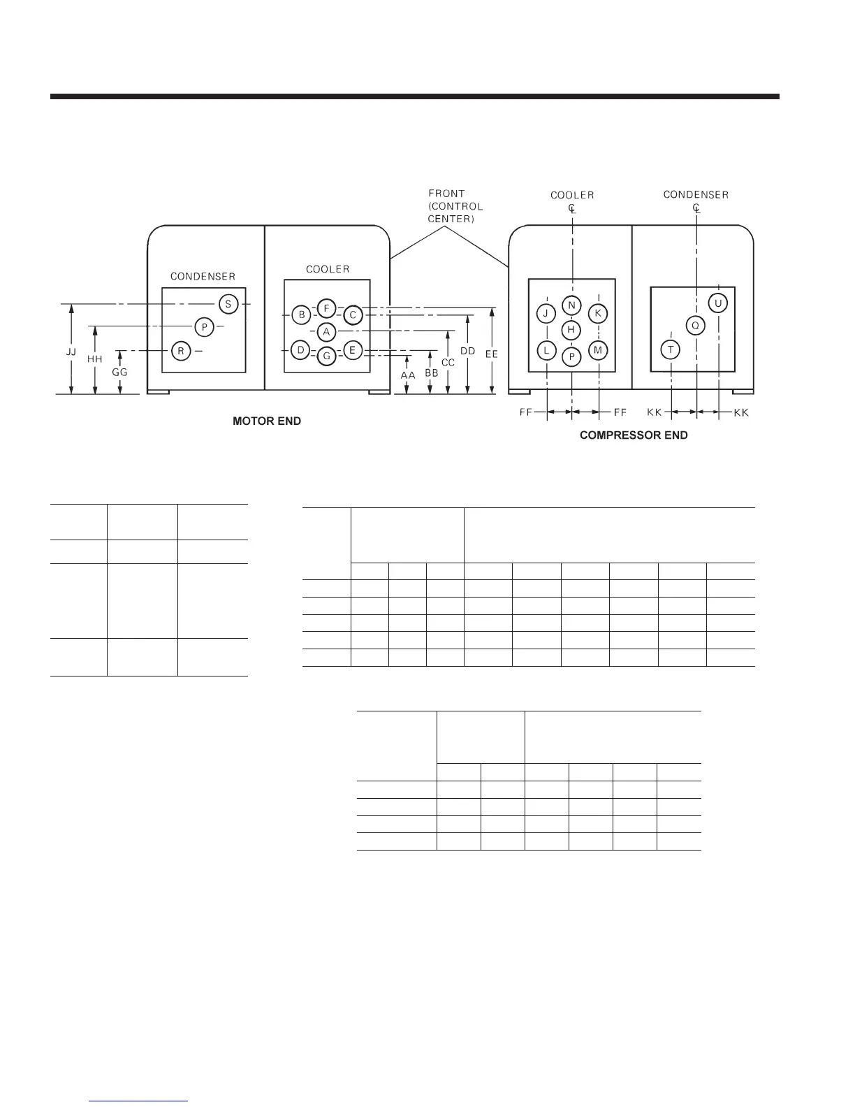
NOZZLE ARRANGEMENTS
CONDENSER NOZZLE DIMENSIONS
NOTES:
1. All dimensions are approximate (shown for 150 psig DWP water side). Certied dimensions are available on request.
2. Standard water nozzles are furnished as welding stub-outs with ANSI/AWWA C-606 grooves, allowing the option of welding, anges, or use of
ANSI/AWWA C-606 couplings couplings. Factory installed, class 150 (ANSI B16.5, round slip-on, forged carbon steel with 1/16” raised face), water
anged nozzles are optional. Companion anges, nuts, bolts and gaskets are not furnished.
3. Add 7/8” to all height dimensions to obtain installed height when using neoprene mounts or 1” for optional spring vibration isolator mounts.
4. One, two and three pass nozzle arrangements are available only in pairs shown and for all shell codes. Any pair of evaporator nozzles may be
used in combination with any pair of condenser nozzles.
5. Condenser water must enter the water box through the bottom connection for proper operation of the subcooler to achieve rated performance.
6. Cooler water must enter the water box through the bottom connection to achieve rated performance.
7. Connected piping should allow for removal of compact water box for tube access and cleaning.
COOLER NOZZLE DIMENSIONS
COMPACT WATER BOX NOZZLE ARRANGEMENTS
R-22 & R-134a UNITS
no. oF
PassEs
CooLEr
In-out
Cond.
In-out
1
A-H
H-A
P-Q
Q-P
2
E-B
D-C
M-J
L-K
R-S
T-U
3
P-F
G-N
CooLEr
CodE
noZZLE
sIZE (In.)
no. oF PassEs
dIMEnsIons (In.)
1 2 3 aa BB CC dd EE FF
B
8 6 4 10 11 3/4 14-3/4 17-3/4 19-1/2 5
C
10 6 6 12 3/4 13 7/8 16 3/4 19 5/8 20 3/4 5 7/8
d
12 8 6 12 7/8 15 1/4 19 1/4 23 1/4 25 7/8 6 5/8
E
12 8 6 12 7/8 15 3/8 19 3/8 23 3/8 25 7/8 7 1/2
F
14 10 8 14-5/8 17 1/2 22 1/4 27 29 7/8 9 1/4
CondEnsEr
CodE
noZZLE
sIZE (In.)
no. oF PassEs
dIMEnsIons (In.)
1 2 GG hh JJ KK
B
8 6 13 16 3/4 20 1/4 4 1/2
C
10 8 11 1/2 16 3/4 22 1/8 4 3/8
d, E
12 10 14 1/4 20 25 7/8 6
F
14 12 17 24 1/2 32 7 3/4

 Loading...