43JOHNSON CONTROLS
FORM 160.80-EG1 (808)
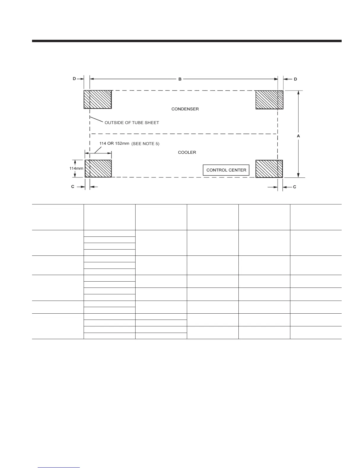
FLOOR LAYOUT – NEOPRENE ISOLATORS
R-22 & R-134a UNITS
NOTES:
1. All dimensions are approximate. Certied dimensions are available on request.
2. Service clearance must be allowed as follows:
610mm at rear (condenser side) of unit and overhead.
915mm at front (evaporator/control center side) of unit.
3050mm (3660mm on S4/S5 compressor) on either end of unit for tube cleaning or replacement. A doorway or properly located
opening may be used.
610mm on either end to allow for removal of water boxes for tube access and cleaning.
3. No special foundation required. Floor must be at and level within 6mm, capable of carrying the operating weight of the unit.
4. Unit has four steel plate foot supports located under the tube sheets at each corner of shell package. Neoprene isolator pads are
eld installed between foot support and oor.
5. All four neoprene isolator pads are identical. Pads are 25mm thick. Unit operating weights under 7423 kg. use 114mm x 114mm isolators; weights
above 7423 kg. use 114mm x 152mm isolators.
6. Loading per isolator pad equals operating weight divided by four.
CoMPrEssor
shELL
CodEs
EVaP. - Cond.
a
tuBE shEEt
WIdth
B
shELL LEnGth
(to outsIdE oF tuBE
shEEts)
C
EVaP
sIdE
d
CondEnsEr
sIdE
s0, s1
B-B
1292MM 3048MM 48MM 64MM
B-C
C-B
C-C
s2
B-B
1588MM 3048MM 48MM 64MMB-C
C-B
s2, s3
C-C
1588MM 3048MM 48MM 64MM
C-D
D-C
1588MM 3048MM 48MM 64MM
D-D
s4
D-C
1880MM 3048MM 48MM 64MM
D-D
s4, s5
E-E 1880MM
3658MM 48MM 64MM
E-F 1943MM
F-E 1994MM
3658MM 48MM 64MM
F-F 2057MM

 Loading...