(CH) with a 10 A fuse in series.
F2 PAUX Positive of the auxiliary output.
F3 PHYDRO Positive for the hydraulic steering contactor.
F4 4th SPEED Input for fourth speed request; it is active HIGH.
F5 SAFETY If not connected to -Batt the MC coil power output will
be disabled. It can also be used as a general purpose
input.
F6 PTHERM Input for motor temperature sensor.
F7 CM Common of LIFT ENABLE / 1st SPEED / 2nd SPEED /
3rd SPEED / 4th SPEED / HYDRO / SR
microswitches.
F8 NAUX This output can be used for drive the main contactor
coil (single pump configuration) or to drive an auxiliary
load (combi configuration)
F9 NHYDRO Output for driving an hydraulic steering contactor; it
drives the load to -Batt. Maximum current: 3 A.
F10 2nd SPEED Input for second speed request; it is active HIGH.
F11 GND -Batt.
F12 NTHERM -Batt.
4.6 Encoder installation
1) AC-2 card is fit for different types of encoder. To control AC motor with Zapi
inverter, it is necessary to install an incremental encoder with 2 phases
shifted of 90°. The encoder power supply can be +5 or +12 V. It can have
different electronic output.
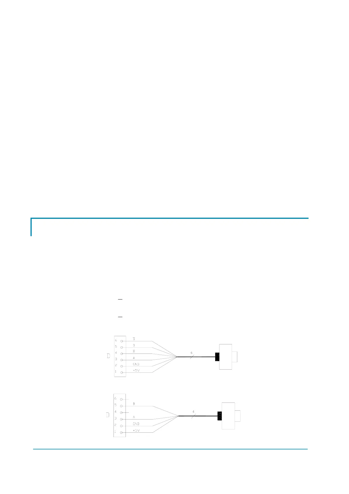
D1 +5 V/+12 V positive of encoder power supply.
D2 GND negative of encoder power supply.
D3 A phase A of encoder.
D4
phase A inverted (encoder with differential output).
D5 B phase B of encoder.
D6
B
phase B inverted (encoder with differential output).
2) Connection of encoder with differential outputs; +5 V power supply.
3) Connection of encoder with open collector output; +5 V power supply.
Page - 18/64 ADEZP0AE - AC-2 INVERTER - User Manual
 Loading...