Network Connection
All network and control cables should enter the dimmer through the segregated route at the bottom of the dimmer.
Segregation between control data cabling and power wiring should be maintained for reasons of safety and noise
immunity.
Control data cabling should be run in separate or divided metal trunking or conduits. Where cables are run outside
trunking or conduits there should be 300mm separation between them and where they cross they should do so at right
angles. All devices in the Chilli network must be connected in serial. The devices in the network can be wired in any
order.
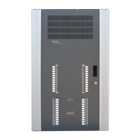
ChilliNet Terminals
Inside the dimmer, the terminals for network connections use two-part
connectors. Pull the connector from the PCB, connect the wires from
the CAT 5 cable and push the connector back onto the PCB, ensuring
correct orientation.
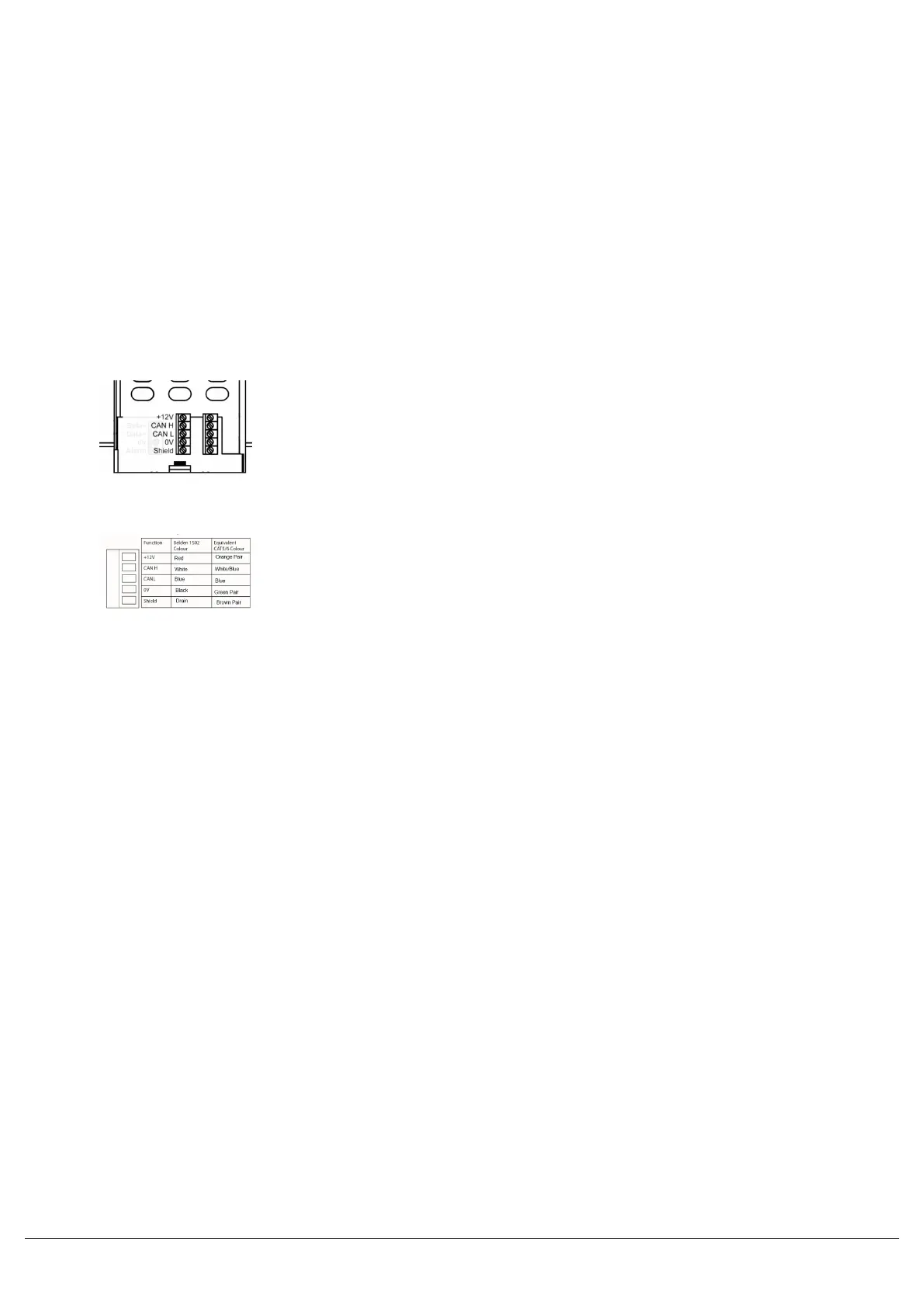
The Chilli Net terminals are labelled with the recommended colours of
the pairs in CAT5 cable, however Belden 1502 cabling may be used.
Termination Resistors
At the two ends of the Chilli network, a network termination resistor must be fitted. Each Chilli Dimmer is supplied with
a termination resistor fitted. This resistor is 120 ohms, 0.25 Watt and is connected between the CAN-H and CAN-L
terminals.
This resistor must be removed, unless the dimmer is at either end of the Chilli network.
Zero 88 - Chilli Pro - Page 11 of 60 Printed: 23/03/2021 09:13:40 ES
 Loading...