Chapter 2 – Overview of ACH 500 Programming
2-2 ACH 500 Programming Manual
Menu System of
Parameters
The parameters in the ACH 500 are organized via a system of menus. There
are four levels of information, plus a start-up data menu. The four levels are:
Operating Data, Main Level, Group Level, and Parameter Level. Each is
described in this chapter.
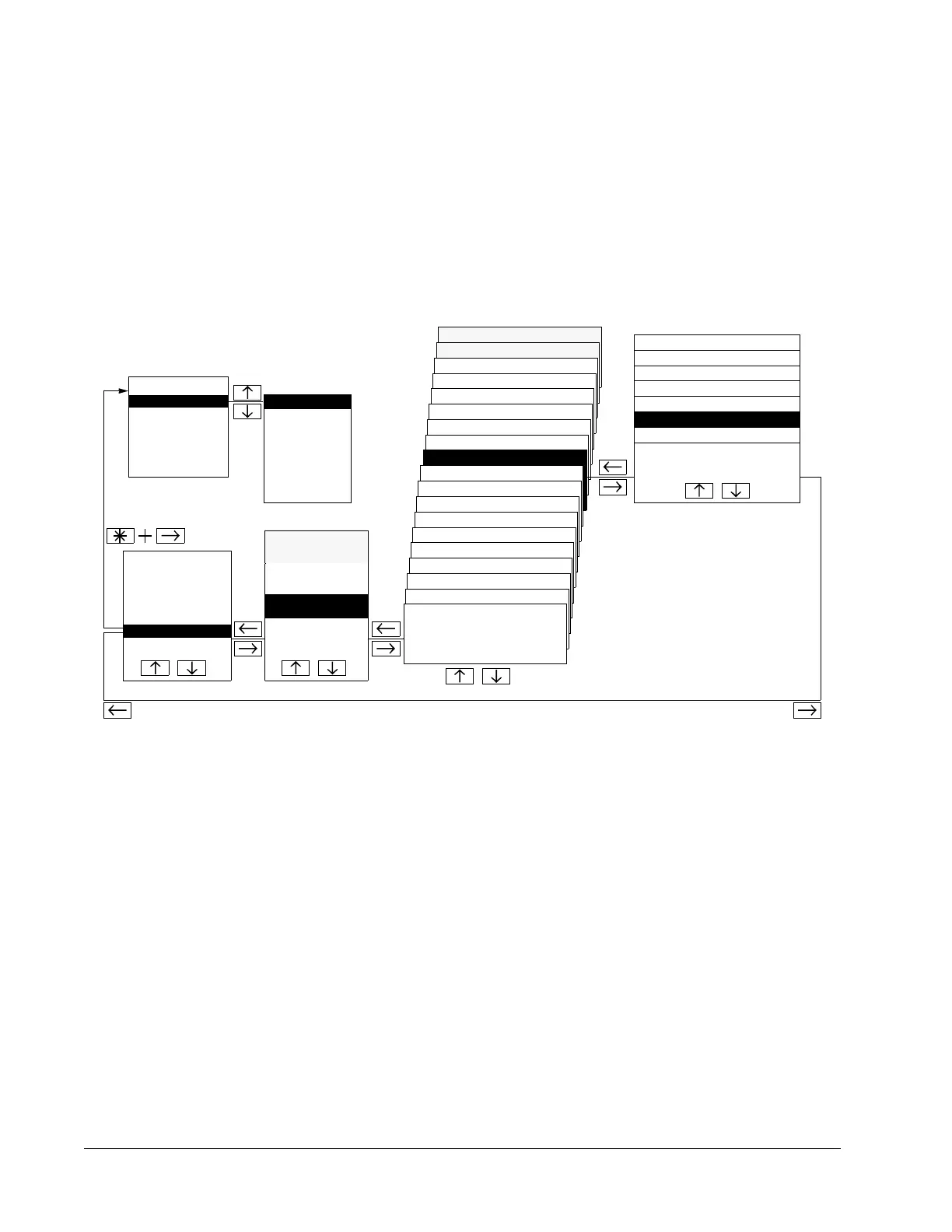
Figure 2-1 shows how to select Start-up Data parameters, Operating Data
parameters, Application macros, Main, Group, and Parameter levels using the
Control Panel keypad.
Figure 2-1 Parameter Selection
Start-up Data
Parameters
The Start-up Data menu contains some basic settings needed to match the
ACH 500 with your motor and to set the Control Panel display language. This
menu also contains a list of pre-programmed Application macros. The Start-
up Data menu is the first menu you modify to start-up your drive.
40.2 PUMP & FAN CONTROL
40.1 PI-CONTROL
30.4 INFORMATION
30.3 SUPERVISION
30.2 AUTOMATIC RESET
30.1 FAULT FUNCTION
20.5 CRITICAL FREQUENCIES
20.4 MOTOR CONTROL
20.3 ACCEL/DECEL
20.2 START/STOP
20.1 FREQ/CURRENT LIMITS
10.8 EXT COMMUNICATION
10.7 ANALOG OUTPUTS
10.6 RELAY OUTPUTS
10.5 ANALOG INPUTS
START-UP DATA
C APPLIC.
RESTORE
D Supply Voltage
20 PARAMETER LOCK
.
.
.
.
30 PROTECTION
PARAMETERS
10 CONTROL
CONNECTIONS
10.4 SYSTEM CONTR INPUTS
10.3 PRESET SPEEDS
10.2 EX REFERENCE SELECT
10.1 START/STOP/
DIRECTION
20.3.8 DECEL REF2 TIME
20.3.7 ACCEL REF2 TIME
20.3.6 DECEL TIME 2
20.3.5 ACCEL TIME 2
20.3.4 DECEL TIME 1
20.3.3 ACCEL TIME 1
20.3.2 ACC/DEC RAMP SHAPE
20.3.1 ACC/DEC 1 OR 2 SEL
OPERATING DATA MAIN LEVEL GROUP LEVEL
PARAMETER LEVEL
1 OUTPUT FREQ.
2 MOTOR SPEED
PARAMETERS
20 DRIVE
A LANGUAGE
APPLICATION
1 HVAC
MACROS
2 FLOAT PT.
3 HVAC – PI
4 P&F AUTOM.
.
B APPLICATION
.
.
.
.
.
.
.
40 APPLICATION
PARAMETERS
 Loading...


