Chapter 6 – Parameters
ACH 500 Programming Manual 6-23
1 SWITCHING FREQ
Motor noise can be minimized by adjusting the switching frequency to a
value that does not create resonances in the motor and load. The optimum
switching frequency is the lowest frequency where the noise is acceptable.
As the switching frequency goes up, the inverter efficiency goes down, so it is
best to use as low a switching frequency as possible relative to acceptable
noise levels for the particular application.
Note: Consult factory for derating information for increased switching
frequency above 3 kHz.
2 MAX OUTPUT
VOLTAGE
Maximum voltage that the drive will output at and above the Field Weakening
point. This parameter is automatically set to the same value as Start-up Data
Parameter K (Motor Nom. Voltage) when that parameter is changed. Set in
actual volts, step equals 1% of V
N
. Range is 0.15 – 1.05 x V
N
.
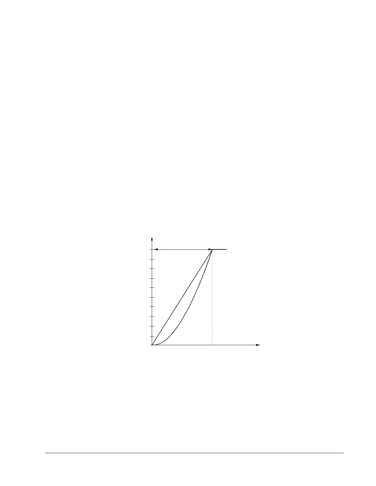
3 V/Hz RATIO
LINEAR
The voltage of the motor changes linearly with frequency in the constant
torque area. Linear V/Hz ratio is normally used in Torque control mode, or
where the torque characteristics of the load is constant with speed.
Figure 6-6 shows V/Hz ratios.
Figure 6-6 V/Hz Ratios
SQUARED
A squared V/Hz ratio undermagnetizes the motor, reducing noise and motor
losses. Squared V/Hz ratio is normally used in applications where the load
torque characteristic is proportional to the square of the speed, such as
centrifugal pumps, fans and compressor drives.
f [Hz]
0
Constant Torque Range
10
50
100
[%]
V
MAX /VN
Linear
V/Hz Ratio
Squared
V/Hz Ratio
Field Weakening Point
 Loading...


