84 ACS2000 DFE UM 3BHS360367 ZAB E01 REV. K
6.9 Power cables, ground cables,
equipotential bonding conductor
The method to prepare the cables for connection to their
corresponding busbars is described below.
6.9.1 Further information 6.9.2 Preparing the cable entry and the cables
Determining the cable length
1. Determine the required length of a cable
between the point of entry and the connection
point inside the cabinet.
2. Cut the cable to the required length before con-
nection.
Preparing cables for 6-hole entry plates
Prepare the cable termination as illustrated in
6-5: B.
See mechanical drawings for information
on:
• Project-specific cable entry
• Distance between the point of cable
entry and the termination bars
• Busbar and fastening hole dimensions
• Busbar designations
See wiring diagrams for information on:
• Conventions for cross-references and
device identification
6-5
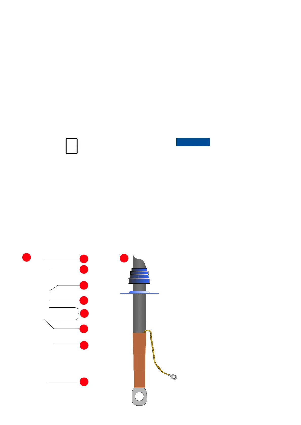
1. Outer cable sheath
2. Grommet
3. Entry plate
4. EMC sleeve
5. Conductor insulation removed to
expose cable shield
6. Cable tie
7. Conductor screen extension to be
connected to PE ground busbar
8. Heat-shrinkable termination
1
2
3
4
5
6
7
8
A
B
6-5 Preparing power
cables for EMC plates
Risk of damage or malfunction!
Waste inside the cabinet can cause damage or mal-
function.
If possible, do not cut cables inside the terminal
compartment. Retrieve any waste which acciden-
tally dropped into the cabinet.

 Loading...


