EasyManuals Logo

ABB ACS580-01 Series User Manual

ABB ACS580-01 Series
84 pages
To Next Page IconTo Next Page
To Previous Page IconTo Previous Page
Page #35 background imageLoading...
Page #35 background image
Mechanical installationFrames R4 and R5 35
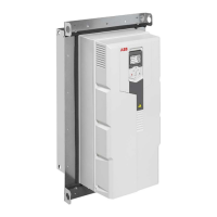
Flange mounting kit package contents
The drawings below show the layout of the flange mounting kit packages. Examine
that all items are present and there are no signs of damage.
Mounting template
The flange mounting kit package includes a template in actual size for drilling the
attaching holes and cutting the hole in the mounting plate.
Item Description Item Description
1 Tightening brackets 9 Bottom bracket
2 Top and bottom U-brackets 10 Side brackets
3 Top cardboard cover 11 Quick guide
4 Cardboard tray 12 Hood (required for UL Type 12)
5 Sealing plug R4 13 Screw package:
M5x20 screw (4 pcs)
M6x25 screw (16 pcs) *
M6 nut (23 pcs)
6 Clamp plate R5
7 Mounting template
8 Top bracket
9 Bottom bracket
*The delivery does not include the Rivet or Kalei nuts for the M6 screws.
10
3 1
1113
12
3AXD50000038137
4
8
9 725
6

Table of Contents

Other manuals for ABB ACS580-01 Series

Questions and Answers:

Question and Answer IconNeed help?

Do you have a question about the ABB ACS580-01 Series and is the answer not in the manual?

ABB ACS580-01 Series Specifications

General IconGeneral
SeriesACS580-01
CategoryDC Drives
Output Voltage0 to Input Voltage
Output Power Range0.75 kW to 250 kW
Communication ProtocolsModbus RTU
Protection FeaturesOvercurrent, overvoltage, undervoltage, overload, short circuit, overtemperature
Enclosure RatingIP21
Ambient Temperature Range-15 to 50 °C
DimensionsVaries by model (refer to datasheet for specific dimensions)
WeightVaries depending on frame size
Control MethodScalar Control (V/f)

Related product manuals