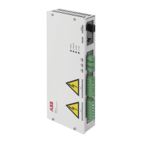
■ Current measurement connections (XIU, XIV, XIW)
Pin descriptions of connector XIU are given in the table below.
DescriptionDirectionNamePin
U-phase current inputInIN1
U-phase current outputOutOUT2
Pin descriptions of connector XIV are given in the table below.
DescriptionDirectionNamePin
V-phase current inputInIN3
V-phase current outputOutOUT4
Pin descriptions of connector XIW are given in the table below.
DescriptionDirectionNamePin
W-phase current inputInIN5
W-phase current outputOutOUT6
Use cable that withstands the measured current and is rated for the voltage in the measured
circuit. Recommended conductor cross section is 1…2.5 mm
2
.
Tightening torque: 0.5…0.6 N·m.
Note: In current measurements, make sure that the current transformers are wired in the
correct direction (see wiring example on page 20).
■ Power supply connection (XPOW)
Pin descriptions of power supply connector are given in the table below.
DescriptionDirectionNamePin
+24 V DC supply voltageIn+24V1
DC neutralIn0V2
GroundInGND_S3
Recommended conductor cross section is 1…2.5 mm
2
.
Tightening torque: 0.5…0.6 N·m.
■ Communication link connection (V30)
Transmitter V1T, receiver V1R
Optical communication link: Avago Versatile Link series optical transmitters & receivers,
DC-50 MBd (50 Mbd/s)
■ Connection to BCU control unit
Connect BAMU-12C auxiliary measurement unit to the first unused channel of the BCU
control unit with fiber optic cables. For parameter settings, see ACS880 IGBT supply control
program firmware manual (3AUA0000131562 [English]).
Installation 19

 Loading...