40
Schutz eingebaut in Schutz durch Schutz durch PT 100
Protection fitted in
Bimetallkontakte Thermistoren
Bi-métal (klixon type) Thermistor protection
max 250 V AC max 2,5 V DC max 2,5 V DC
1 Schutz (Auslösung) Hilfspole
1 protection (trip) interpoles
2 Auslösunggen 1 in Hilfspole
oder 2 Alarme
1 in interpoles
2 protections
1 im Hauptpol 2 in serie 2 in serie
(2 trip or 2 alarms) 1 in main poles 2 in series 2 in series
2 Schutz (Warnung + Auslösung) 2 in Hilfspolen
2 protection (alarm + trip) 2 in interpoles
Bezeichnung -
Marking
Überwachung -
Observations
Heizelement
Heating element
110 V oder 220 V (± 5 %) -
110 V ou 220 V (
±
5 %)
Bremsenüberwachung
24 V oder 207 V (DC) als standard (+ 5 % / - 10 %) andere Spannungen auf Anfrage
Brake control 24 V or 207 V (DC) as standard (+ 5 % / - 10 %) other voltages on request
Positionsanzeige der Bremsscheibe Max 308 V, 10 A (AC) / 487 V, 1 A (DC)
Brake disk position indicator
Bürstenabriebüberwachung Widerstandslast /
Resistive load :
max 3 A, 220 V (AC) / 7 A, 28 V (DC)
Brush wear sensor
Induktive Last /
Inductive load :
max 2 A, 220 V (AC) / 4 A, 28 V (DC)
EMK-Messung /
FEM measurement
Connection of cables
DMP motors are supplied with the terminal box mounted
on either side or on top of the machine.
Tightening torques for cable connections inside the
terminal box are:
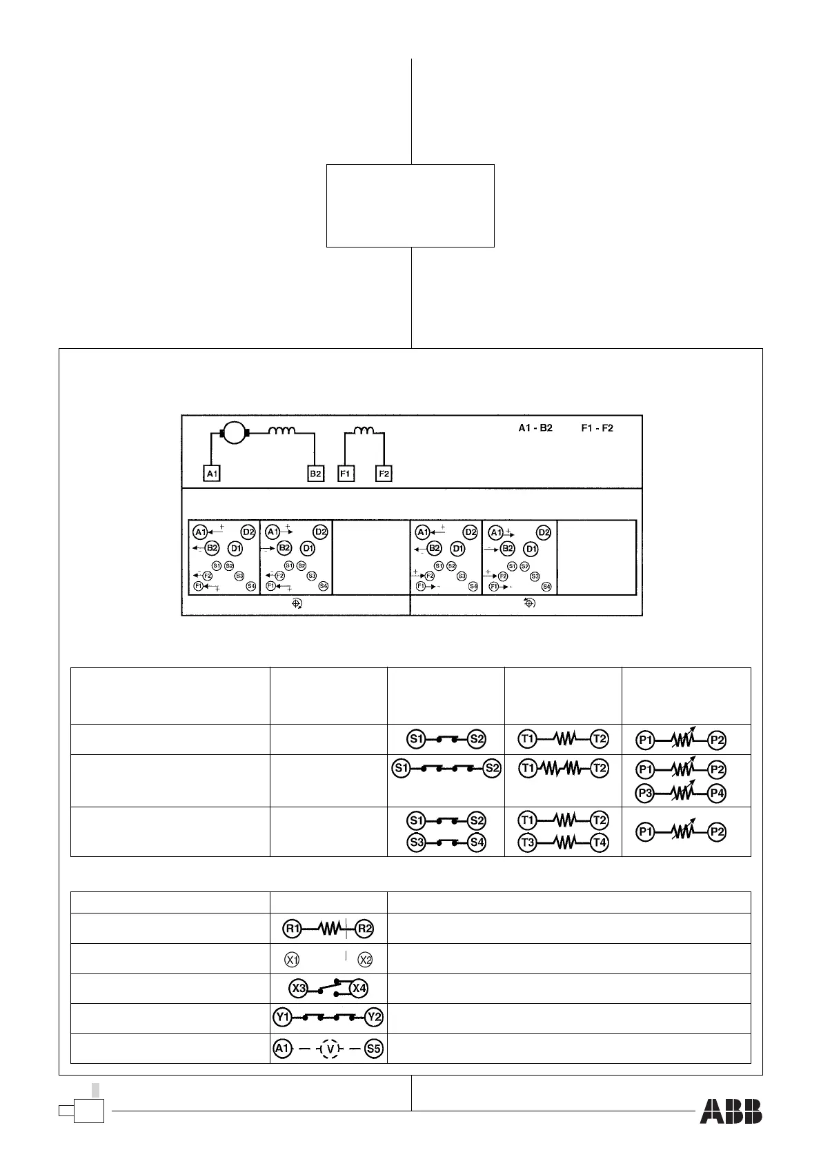
■ Terminal diagram
Refer to diagram for shunt wound DC motors.
Klemmenauschlussplan, DMP Standardausführung
Terminal diagram, DMP Standard design
Bezeichnung des Temperaturschutzes der Wicklungen
Marking of windings temperature protection
Anderes Zubehör -
Other accessories
Anker
Armature
Erregung
Shunt
Nebenschluss -
Shunt
DC Motor DC Generator DC Motor DC Generator
Fig. 1 Fig. 2 Fig. 3 Fig. 4
Kabelanschluß
Die Klemmenkästen der DMP-Motoren können wahlweise
auf eine der beiden Motorseiten oder auf dem Motor
montiert werden. Zulässige Anzugsmomente für die
Kabelschuhe der Anschlusskabel im Klemmenkasten :
■ Klemmenanschlussplan
Bezieht sich auf den Anschlussplan von
Gleichstromnebenschlussmotoren.
43 Nm für/
for
M 12
30 Nm für/
for
M 10
13 Nm für/
for
M 8
5,3 Nm für/
for
M 6
1,2 Nm für/
for
M 4
 Loading...
