Sensor Wells
Model Sensor Type Sensor Well
½ in. rigid
¾ in. pipe (typical)
½ in. flexible stainless
½ in. rigid
The compression fittings that hold the sensor inside the sensor
well contain TEFLON® ferrules. It is not necessary to change the
TEFLON® ferrules to metal. This connection will not be required
to retain process pressure.
IMPORTANT (NOTE)
When installing/removing a sensor into/from a sensor well, a
wrench shall be used on both the sensor, and the sensor well.
The sensor installation torque shall not be transferred to the
sensor well.
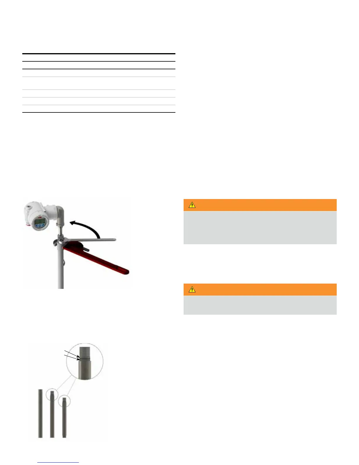
Figure 7 Sensor well installation
Assembly instructions for W7 flexible probes
1 Prepare section joints by lubricating the O-ring and mating
surface of male threaded portion (Figure 8). For detail refer
to “LMT100 PROBE TYPE W7” in Section 11 “Dimensional
drawings”
Apply lubrication
to o-ring and
mating surface
Figure 8 W7 Well Threaded Connection
2 Lower the bottom tube section with the float stop and float
into tank.
3 Insert the top of the tube assembly through the mounting
flange.
4 Add the next section of tube and thread together using
thread locking fluid (Loctite® 242®) to secure joints.
5 Repeat step 4 for each middle tube section.
6 Add the last section (TOP) of the tube with 1 in. compression
fitting, and thread into the assembly using thread locking
fluid (Loctite® 242®) to secure the joint.
7 Thread the tube compression fitting into the mounting
flange using thread sealant.
8 Lower the tube assembly until it hits the bottom of the tank.
Raise the sensor well back up 12mm (½in) and secure the
assembly in place by tightening the tube compression
fitting.
WARNING
When handling flexible tubing, do not bend any section of
the tube into a diameter of less than 4 feet. This could
permanently damage the internal assembly and prevent
proper operation.
9 Insert the flexible probe into the tube assembly. Secure
flexible probe assembly to stainless-steel tube using 1in tube
to 1in tube compression fitting.
WARNING
Ensure that the assembly is tight and properly sealed to
prevent moisture entry.
Mounting the LMT200
When mounting the LMT200 level transmitter, the following
rules need to be applied to ensure proper installation:
• If the LMT Series device was purchased with the KM26
magnetic level gauge (MLG), it will have been shipped
mounted and positioned and will not typically require any
further mechanical adjustment.
• The sensor tube is labeled with a factory zero mark. The line
on this tag should be aligned with the zero on the scale of the
level gauge.