31
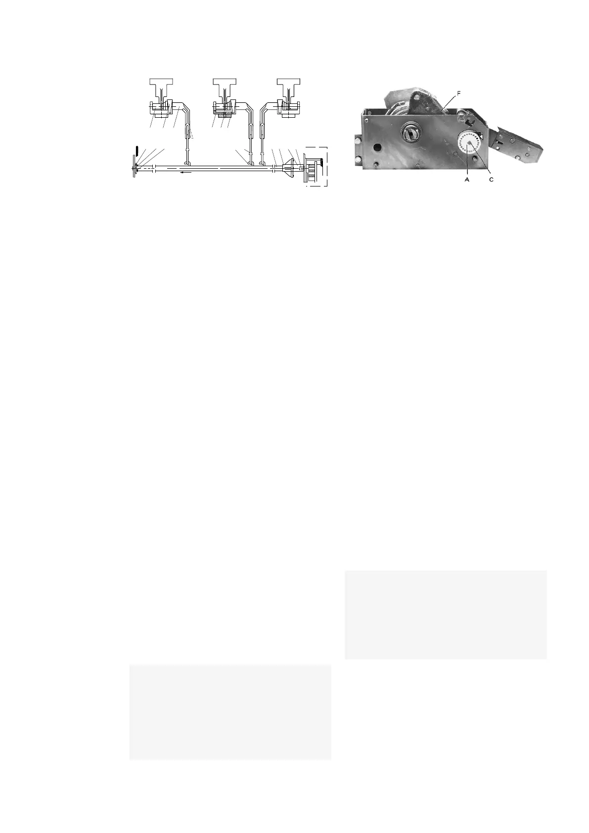
13.2 Mounting of the fuse tripping. Fig. 45
1. Lower part of bearing (8) is fixed to terminal
(10) by one screw (9).
2. The lever (13) together with the fuse trip flap
(15) are placed in the lower bearing (8) and
locked by means of upper part of bearing
(14).
3. The released rod (11) is mounted in the lever
(13).
4. The drive ring (2) is mounted to the release
shaft (1) on the RHS (right hand side).
5. The bearing (5) and washer (6) is mounted on
the release shaft (1) on the LHS (left hand
side) and secured by split-pin (7).
6. Disc (3) is mounted to the release shaft (4) of
the mechanism.
7. The release rods (11) are mounted onto the
hooks (12) on the release shaft (1).
13.3 Adjustment of the fuse tripping. Fig.45.
1. The adjustment applies to switch-
disconnectors with fuse-links and fuse
tripping,
2. The adjustment must be made with both
operating springs in the mechanism in
uncharged position, but the releasing spring
in the mechanism has to be charged as
mentioned under control point 6.4 point
3. The split pin (7) is removed and the release
shaft (1) together with the drive ring (2) is
pushed in the direction of the arrow until the
tapped connection is free from disc (3).
4. The release rod (1) with the drive ring (2) is
turned and adjusted to a hole in the disc (3),
while the adjustment of the fuse trip flap (15)
and its distance to the strike pin of the fuse-
link must be checked, see Fig.43.
13.4 Fuse tripping
1. Turn the operating mechanism shaft
clockwise, max 60°, and return the operating
handle back to the neutral position (opening
spring housing F, see Fig. 46, must not be
latched),
2. Mount a new fuse-link, or a test fuse which is
in accordance with DIN 43625, in one of the
phases. The fuse-links for switch-fuse
combination with fuse tripping system, must
come form NALF/NALFWind 36 reference list
of fuse-links to ensure proper coordination
between switch-disconnector and current
limiting fuse-link breaking performance
characteristic, according to IEC 62271-105.
3. If the distance between the fuse clips of
fuse-bases (see Fig. 43) is longer than
described – max e + 8 mm, the adjustment
(point 13.3) must be made with the fuse-link
mounted on the fuse-base,
4. The distance between the striker pin and the
fuse trip flap (position 15 Fig. 45) must be
from 3-6 mm (see Fig. 43). By this adjustment
the fuse-link is allowed to sag, but the
distance between the striker pin and the fuse
trip flag must not exceed 12 mm,
5. If the fuse switch-disconnector does not
open when adjusted as mentioned above, the
adjustment has to be checked and repeated.
15 14 13
7 5 6
7
12
11
9
8
1 2 3 4
MEC.
10
—
46 A-mechanism
—
45 Fuse tripping completed
_
Remark:
The hooks (12) on the release rod
(1) ought to have the same position as
shown on Fig. 45 - when the fuse-switch
disconnector is in open position with both
operating springs uncharged, but with the
releasing spring charged.
_
Remark:
Following adjustment according
to above the fuse switch-disconnector
must open when tested in all phases.
After fuse interruption the mechanism
shall be blocked against another operation
until the fuselink has been replaced.
 Loading...