59
21.2 Replacement of draw bar. Fig. 117
1. Disconnect the switch-disconnector.
2. Pull out the bolt b.
3. Pull down the auxiliary knife such that the
drawbar bolt (a) can be pushed out and upper
hold for the drawbar is free.
4. The lower mounting for the drawbar is freed
by removing circlips on eccentric bolt, see
Fig.118.
5. New drawbar to be fitted in sequence a-b,
see Fig.117.
—
118 Contact knife
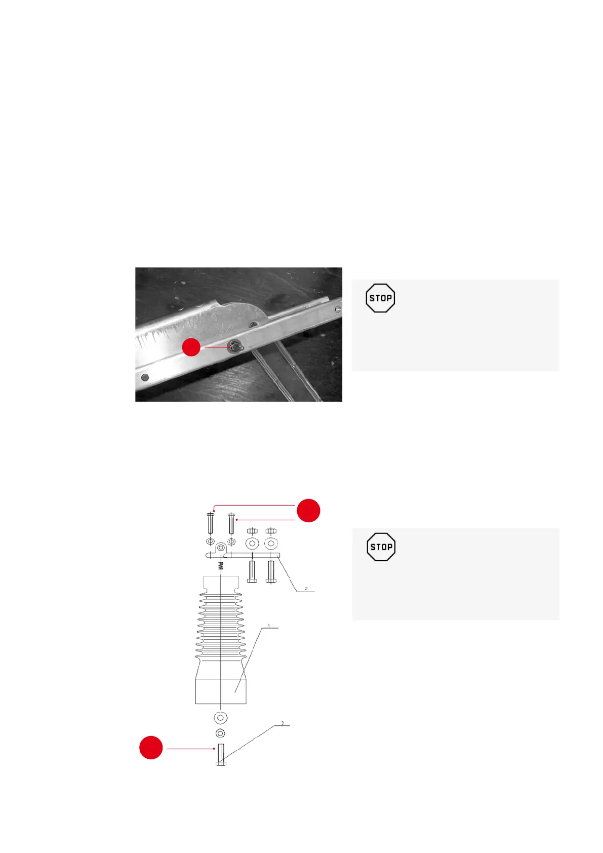
21.3 Replacement of the supporting insulator.
Fig. 119
1. Disconnect the switch-disconnector.
2. Contact block with contact knives is
dismounted (use spanner-gap 17).
3. The insulators are attached to the switch
frame by a screw M12 (spanner-gap 19). The
insulator is dismounted and a new insulator
is mounted to the switch frame.
4. Contact block with contact knives is
mounted to the insulator and adjusted as
described in paragraph "Hollow insulator
with arcing chamber”.
—
119 Replacement of the supporting insulator
b
40 Nm
90 Nm
_
WARNING!
These operations shall be carried out by
authorised ABB service only!
_
WARNING!
These operations shall be carried out by
authorised ABB service only!
 Loading...