7
Connection
diagram
SPAJ 160 C
63 6261
1 A
5 A
1 A
5 A
25 2627123456 789
1 A
5 A
L1
L2
L3
70 71 72
0
65 66
Uaux
+ (~)
- (~)
IRF
68 6977 78
IRF
SIGNAL 1
-
+
TRIP
74 75
SIGNAL 2
80 811011
1 1
SGB/1
SGB/2
SGB/7
SGB/8
SGB/3
TRIP
R
START
RECONNECTION
INHIBIT
1
I
-
I 0
+
+
+
B
+
C
+
F
+
E
+
D
+
A
SGB/4
I/O
3I<
∆I1
RECONN. INHIBIT
1
1
SGB/5
RELAY RESET
SGB/6
EXTERNAL TRIP
SGR1/1
SGR1/2
SGR1/7
U1 SPCJ 4D40
U3
U2 SPTU_R2
CONTROL.
INPUT BS
3I
a
>
TS1 SS1 SS2
SS3
TS2
SGR1/3
∆I2
SGR1/4
SGF/1
SGR1/5
SGR1/8
SGF/2
SGR1/6
SGR2/8
3I
b
>
SGR2/7
SGR2/6
SGR2/5
SGR2/4
SGR2/3
SGR2/2
SGR2/1
1
T8
T2
T5
T4
T3
T6
T7
T9
T1
1 A
5 A
+-
≅
_
SPA-ZC_
Rx Tx
SERIAL
PORT
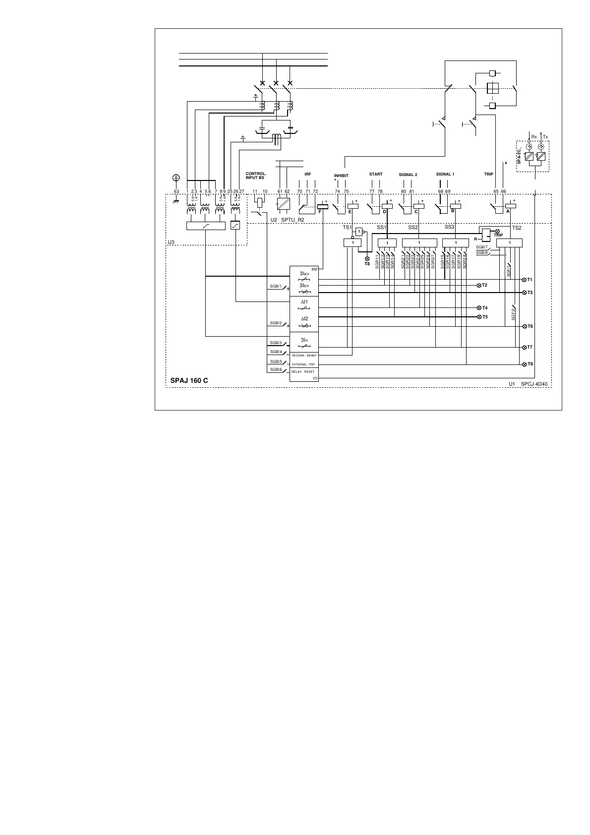
Fig. 8. Complete connection diagram for the capacitor bank protection relay SPAJ 160 C with all
the relay matrix and blocking/control input programming switches shown.
U
aux
Auxiliary voltage
A, B, C, D, E, F Output relays
IRF Self-supervision
SGB1 Switchgroup for the configuration of the blocking and control signals
TRIP Trip output relay, output 65-66
SIGNAL 1 Signal on tripping
SIGNAL 2 Signal on tripping
START Signal on starting
RECONN. INHIBIT Connection inhibited in fault conditions
U1 Capacitor bank protection relay module SPCJ 4D40
U2 Power supply and output relay module SPTU 240 R2 or SPTU 48 R2
with a normally open trip contact
U3 Input module SPTE 4E3
Rx Tx Serial communication interface
T1...T9 Operation indications
SPA-ZC- Bus connection module

 Loading...


