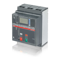
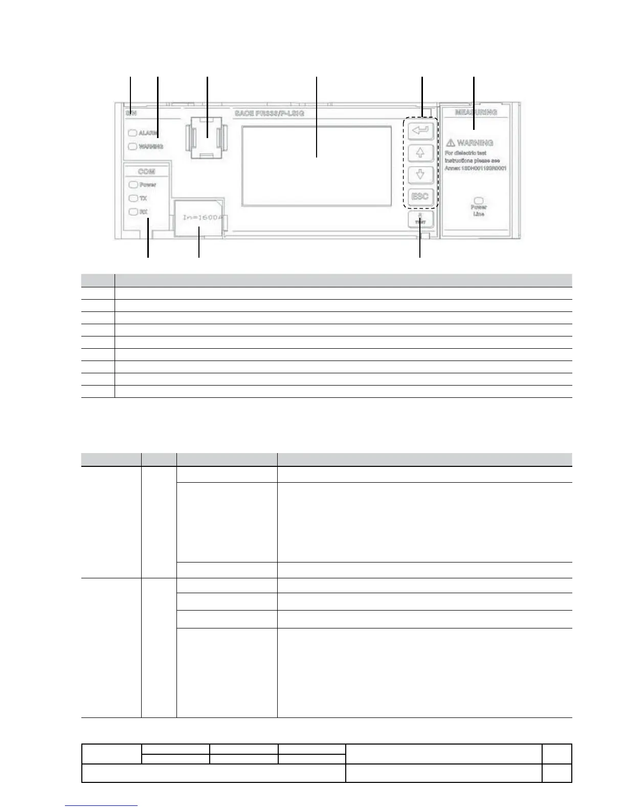
3.4. User interface
A graphic display and a push-button panel provide all the available settings and information.
1 2 4
8 7
6
5 3
9
Ref. Description
1 Serial number of the protection release
2 State led
3 Test connector
4 Graphic display
5 Main push-button panel
6 Label and Led of internal module PR330/V
7 Label and Led of internal module PR330/D-M
8 Rating plug
9 “i Test” button
3.4.1. LEDs
The 2 front leds provide information about the state of the protection release and CB.
Both leds function when the unit is on.
Signal Colour State Description
ALARM Red
OFF No protection or delay alarm
ON (Flashing @1Hz)
Delay in progress for one or more of the following protections: current (L,
S, G), voltage (UV, OV, RV), frequency (OF, UF), active power reversal (RP),
phase unbalance (U)
Alarm for one or more: Contact wear, Temperature
Connection error of one or more: Rating Plug, Trip Coil , Key plug error,
Current sensors
Installation error
ON (Fixed) Internal error (ABB assistance required)
WARNING Yellow
OFF No CBB error or alarm
ON (Flashing @0.5Hz) OT protection in prealarm
ON (Flashing @1Hz) OT protection in alarm state
ON (Fixed)
Protection L prealarm
Protection U alarm with trip disabled
Distorted wave form with > 2.1 Form factor
Contact wear within range: 80%<CW<100%
Iw WARNING threshold exceeded
CB state error
Frequency off range
Configuration error
Incongruent settings
B1751
 Loading...