3.10.1.3. Voltage transformer
In the case of three-phase systems with a rated voltage greater than 690 Vrms phase to phase or with a PR330/V module con-
nected by external sockets, a step-down transformer (with a transformation ratio of less than 1).
Proper operation is only guaranteed for star/star or delta/delta configurations.
The allowable primary and secondary rated voltages that must be set on the unit are specified.
Standard single transformers:
Mechanical characteristics
Fixture DIN rail EN 50022
Material self-extinguishing thermoplastic
Degree of protection IP30
Electrostatic protection shielded towards EARTH
Electrical characteristics
Precision class cl. 0,5
Performance ≥10VA...≤20 VA
Overload 20% permanent
Insulation 4 kV between inputs and outputs
4 kV between inputs and outputs
4 kV between inputs and inputs
Operating frequency range from 50 Hz to 60 Hz, ± 10%
The following is a summary table of standard VT connections according to the type of plant.
The VTs must have a performance coming between the values of 10 and 20VA inclusive, 4 kV insulation between the primary
and secondary.
Installation system
"VT Standard" type transformer
(Star/Star)
"VT Standard" type transformer
(Delta/Delta)
Application diagram Application diagram
TN-C B A
TN-S B A
IT with neutral B A
IT n.c A
TT with neutral A B
TT without neutral n.c A
Note for B diagram:
- for TN-C systems the connection must be made to PEN
- for TN-S systems the connection must be made to N for configurations with neutral or PE for configurations without neutral; if
the PE is used, the current thereon could be around a dozen mA. If a customer considers this value too high or has a residual
current protection which risks being tripped, then application diagram A must be used.
- for IT and TT systems with neutral, the connection must be made to N.
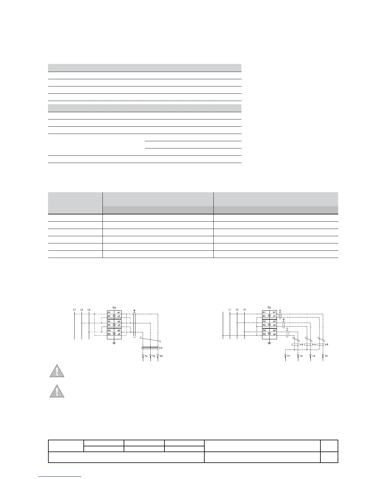
Application diagram B
Application diagram A
WARNING: The maximum length of the VT - PR330/V wiring must not exceed 15 meters.
Use corded shielded two-wire cable (e.g. BELDEN 3105A two-wire cable).
The shield must be connected to earth on both sides.
WARNING: Dielectric strength tests must not be performed on the inputs and outputs of the protection release
and on the secondary lines of any VT connected.
B1751
 Loading...