Operating instruction manual | TX Thermal Disperson Level Switches 17
8.0 TEMPERATURE SWITCH OPTION
In the temperature switch conguration, the heater can be disabled and the active RTD is not used. The reference RTD
is used to measure the temperature of the process medium. The resistance of the reference RTD is directly propor-
tional to temperature. The unit is shipped with the default settings unless otherwise stated on the order. A temperature
set point can be veried or changed by placing a resistance decade box across pins 1 & 2 of connector P2. Pin 1 is
located closest to the edge of the board. Once the desired set point temperature has been decided, the resistance of
the decade box can be used to set the point where the relay energizes (LED on):
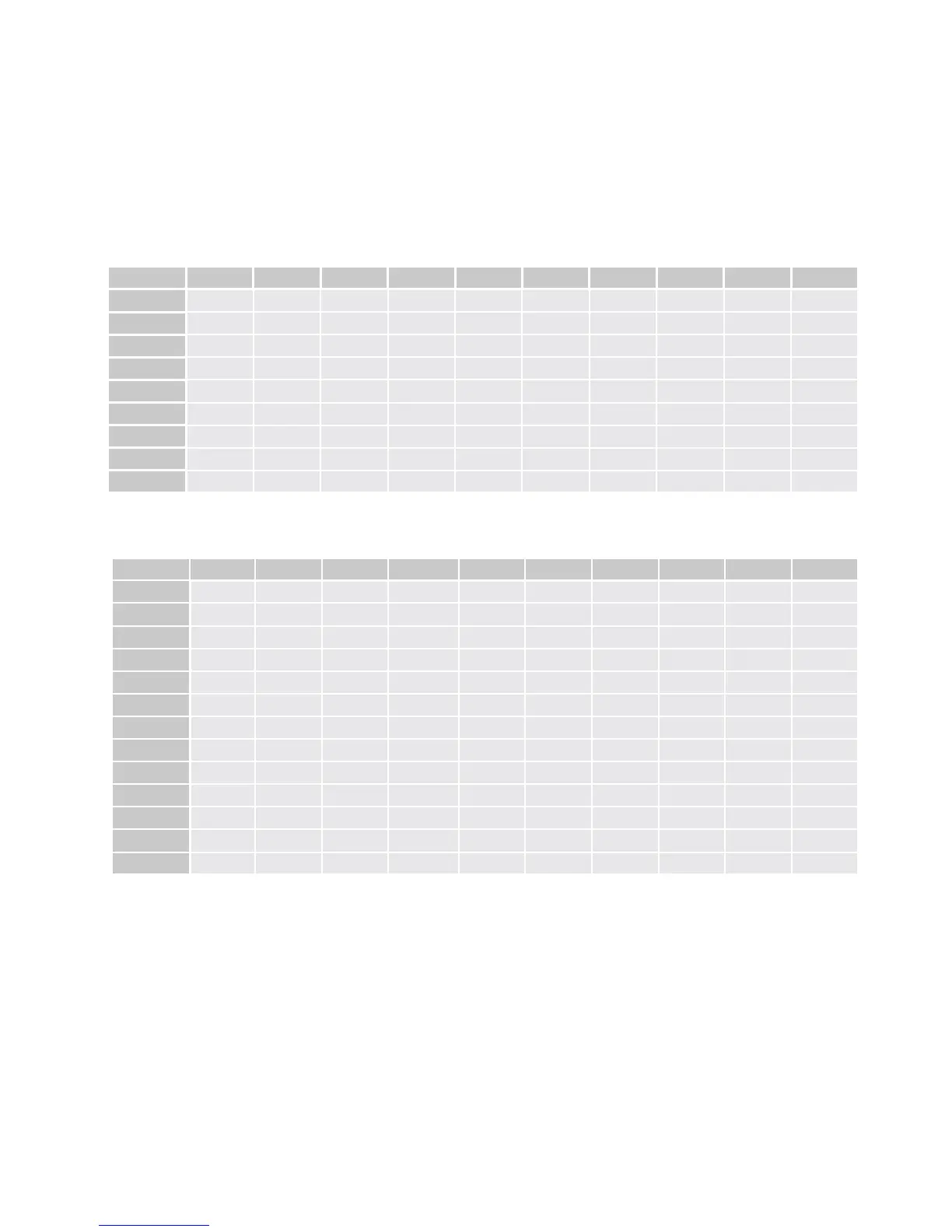
TABLE 1: OHMS / Deg. F for silicone temperature sensor - Standard
Resistance calculation = [(0.0053(temp in degrees F) ²) + 3.4187(temp in degrees F) + 704.99] ohms.
TEMP F 0 +5 +10 +15 +20 +25 +30 +35 +40 +45
-50 547 562 577 592 607 623 639 655 671 688
0 705 722 740 757 775 794 812 831 850 870
50 889 909 929 950 970 991 1012 1034 1056 1078
100 1100 1122 1145 1168 1192 1215 1239 1263 1287 1312
150 1337 1362 1388 1413 1439 1466 1492 1519 1546 1573
200 1601 1629 1657 1685 1714 1743 1772 1801 1831 1861
250 1891 1921 1952 1983 2014 2046 2078 2110 2142 2175
300 2208 2241 2274 2308 2342 2376 2410 2445 2480 2515
350 2551 2587 2623 2659 2695 2732 2769 2807 2844 2882
TABLE 2: OHMS / Deg. F - HIGH TEMP OPTION (/H1 or /H2): (Platinum RTD)
Resistance calculation = [(-0.0002(temp in degrees F) ²) + 2.1288(temp in degrees F) + 932.05] ohms.
TEMP F 0 +10 +20 +30 +40 +50 +60 +70 +80 +90
-300 275.4 297.9 320.3 342.7 365 387.4 409.6 431.8 450 476.2
-200 498.3 520.4 542.4 564.4 586.3 608.2 630.1 651.9 673.7 695.5
-100 717.2 738.8 760.5 782.1 803.6 825.1 846.6 868.0 889.4 910.7
0 932.1 953.3 974.5 995.7 1016.9 1038.0 1059.1 1080.1 1101.1 1122.0
100 1142.9 1163.8 1184.6 1205.4 1226.2 1246.9 1267.5 1288.2 1308.8 1329.3
200 1349.8 1370.3 1390.7 1411.1 1431.4 1451.8 1472.0 1492.2 1512.4 1532.6
300 1552.7 1572.8 1592.8 1612.8 1632.7 1652.6 1672.5 1692.3 1712.1 1731.9
400 1751.6 1771.2 1790.9 1810.5 1830.0 1849.5 1869.0 1888.4 1907.8 1927.1
500 1946.5 1965.7 1984.9 2004.1 2023.3 2042.4 2061.5 2080.5 2099.5 2118.4
600 2137.3 2156.2 2175.0 2193.8 2212.6 2231.3 2249.9 2268.6 2287.2 2305.7
700 2324.2 2342.7 2361.1 2379.5 2397.8 2416.2 2434.4 2452.6 2470.8 2489.0
800 2507.1 2525.2 2543.2 2561.2 2579.1 2597.0 2614.9 2632.7 2650.5 2668.3
900 2686.0 2703.6 2721.3 2738.9 2756.4 2773.9 2791.4 2808.8 2826.2 2843.5
Example 1: At (-20 F) (Standard RTD) the resistance is 639 ohms (see table1)
Example 2: Using platinum RTD, the resistance at –20 °F is calculated as follows:
Set Point Resistance = (0.0002)(-20) ² + 2.1288(-20) + 932.05 = 889.6 ohms (Table 2 = 889.4 ohms)
With the resistance decade box connection across pins 1 & 2, adjust R18 until the LED just turns off. Decreasing the
resistance of the decade box now will cause a drop in temperature and resistance, and the relay to energize and the
LED to turn on.
State A is the default conguration for the relay from the factory. Other jumpers must be move to set the switch for
temperature operation. The relay is de-energized (LED off) until the temperature drop below the set point. If it is de-
sired that the relay energize when the temperature rises above the set point then congure JP3 for State B.

 Loading...