18 TX Thermal Disperson Level Switches | Operating instruction manual
9.1 Voltage / Resistance Measurements and Jumper Settings (Main Board)
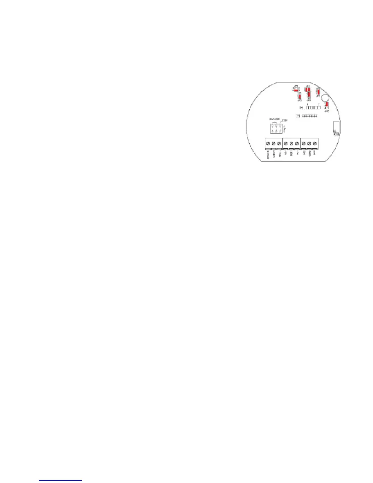
Check JP3 (Main board – bottom board only)
Jumpers set on 2-4, 1-3 (Default setting) (jumpers set vertically) relay to energized (LED ON) below set-point.
• Jumper setting 1-2, 3-4 (jumpers set horizontally) relay to energize (LED ON) above set point
9.2 Procedure for measuring voltage to the sensor using DVM (with power applied)
P2 Sensor Plug – (Pin 1 next to Q3 and toward edge of board)
• Pins 1-2: 1.xx volt DC (Pin 1 – Green or Yellow Wire; Ref Sensor)
• Pins 1-4: 7.xx volts DC
• Pins 2-4: 6 volts DC (Pin 4 -Red Wire; Negative side of PS)
• Pins 3-2: 1.xx volt DC (Pin 2 -Black Wire; Common to RTD )
• Pins 3-4: 7.xx volts DC (Pin 3 – Yellow Wire; Active Sensor)
• Pins 5-4: 17 volts DC on the TX only (Pin 5 – Red Wire)
18.5 volts DC on the TS, TQ, IX and IM
• Pins 1-3: DELTA VOLTAGE = (active sensor vs. reference sensor)
Air - TX ( HO Model) = 350mV, (H1 & H2 Model) = 141mV;
TQ Model = 140mV; TS Model = 460mV; IX Model= 110mV
Water - TX (HO Model) = 30mV, (H1 & H2 Model) = 10mV,
TQ Model = 25mV, TS Model = 90mV, IX Model = 15mV
9.2.1 With power disconnected measure resistance of Heater and Sensors
P2 Sensor Plug (disconnected) – Female Connector (Pin 2 – Black Wire, Common to RTD)
• Pins 4-5: 172 ohms on the TX only (Red Wires)
470 ohms on the TS, TQ, IX and IM (Red Wires)
• Pins 1-2: 1K ohm @ ambient temperature (RTD Reference Sensor) (Green & Black)
• Pins 3-2: 1K ohm @ ambient temperature (RTD Active Sensor) (Yellow & Black)
If the voltage measurements are incorrect then suspect board failure. It resistance measurements are incorrect suspect
probe failure. Please call ABB Service Department for a replacement board or probe. If the voltage and resistance mea-
surements are correct suspect incorrect setup or not allowing enough time for unit to switch. The switch has an inherent
time delay.
OPTIONAL DUAL POINT CIRCUIT BOARD (TOP BOARD)
If the bottom board and sensor measurements are correct and the top board LED goes on and off when the unit is im-
mersed in water, then the set-point is not properly adjusted for the process.
9.0 TROUBLESHOOTING

 Loading...