2TLC172156M0201, rev. C 13 www.abb.com/jokabsafety
2016-07-04
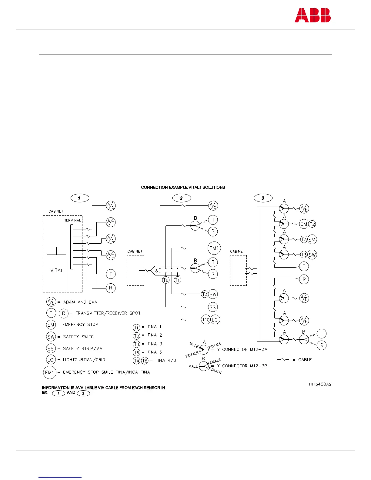
Example connections of units and cable lengths to Vital 1
Three connection alternatives
To comply with PL e according to EN ISO 13849-1, the connection of sensor/adaptor units in the Vital safety circuit
must be made as per the following connection examples.
Example 1
Use separate connection cables from each sensor/adaptor unit and connect them in series to create the Vital
safety circuit through terminals in the control cabinet. Status information is available from each individual sensor at
the terminal.
Example 2
Use Tina 4A/Tina 8A connection blocks to simplify the connection of externally installed sensors/adaptor units.
Only Tina 4A/Tina 8A connection blocks may be used. Use of any other connection block is not recommended as it
may not meet the requirements for the highest safety level. Status information is available from each individual
sensor at the connection block.
Example 3
Use M12-3A and M12-3B “Y-connectors” to connect sensors/units in series or in parallel.

 Loading...