2TLC172156M0201, rev. C 8 www.abb.com/jokabsafety
2016-07-04
Reset connections
It is possible to choose manually supervised or automatic reset on Vital 1.
Warning!
When manually supervised reset is used, the reset button must be placed such that:
It is outside the hazardous area, and cannot be reached from inside the hazardous area.
The entire hazardous area is visible from the reset button.
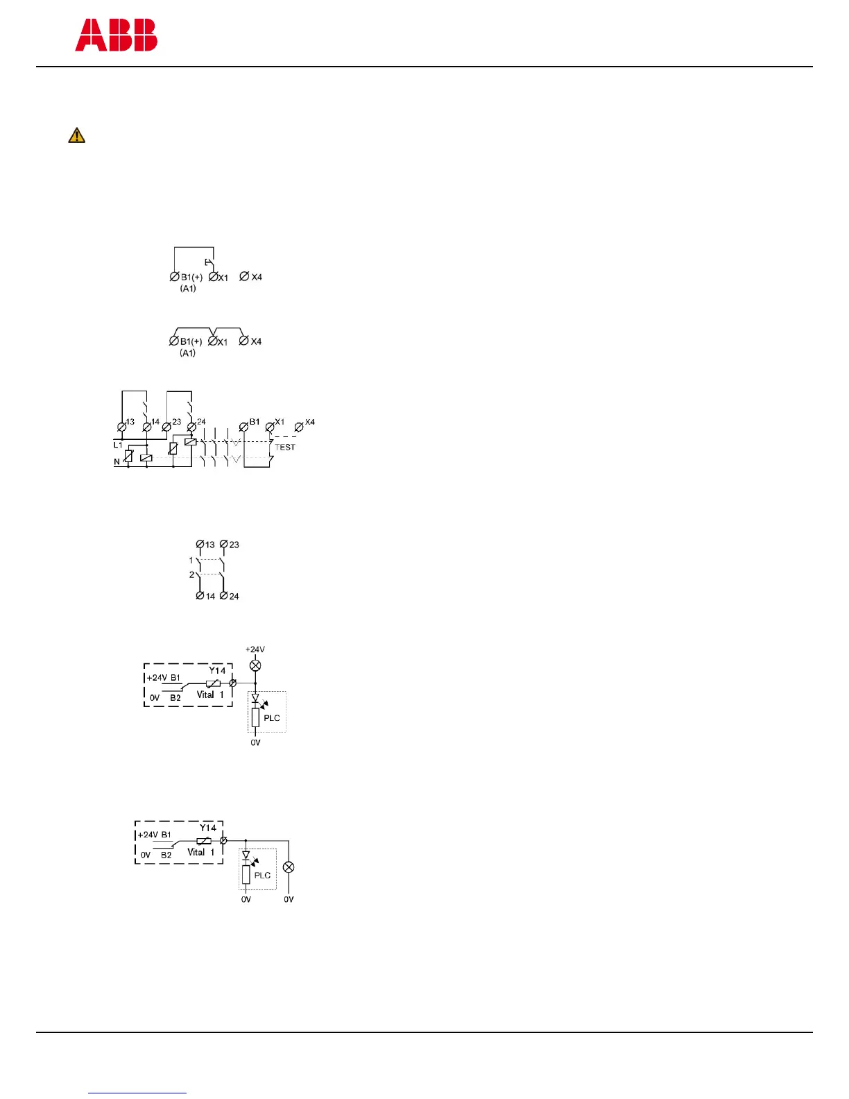
Manually supervised reset
The manually supervised reset contact connected to input X1 must be
closed and opened in order to activate the relay outputs.
Automatic reset
Automatic reset is selected when B1, X1 and X4 are connected. The
relay outputs are then activated at the same time as the inputs.
Testing external contactor status
Contactors, relays and valves can be supervised by connecting ‘test’
contacts between B1 and X1. Both manually supervised and
automatic reset can be used.
Vital 1 has two (2 NO) safety outputs. In order to protect the output
contacts it is recommended that loads (inductive) are suppressed by
fitting correctly chosen VDR’s, diodes etc. Diodes are the best arc
suppressors, but will increase the switch-off time of the load.
Information output, switch position 1 (towards middle)
In switch position 1 (original position) the relay output Y14 is
connected internally to 0 V and +24 V in the following way:
Y14 is internally closed to 0 V (B2) when Vital 1 has not been
reset.
Y14 is internally closed to +24 V (B1) when Vital 1 has been
reset.
Information output, switch position 2 (towards edge)
In switch position 2 (function is for Start/Restart interlock, RES) the
relay output Y14 is connected internally to 0 V and +24 V in the
following way:
Y14 is internally closed to 0 V (B2) when the dynamic safety
circuit is open or when the dynamic safety circuit is closed and
Vital 1 has been reset.
Y14 is internally closed to +24 V (B1) when the dynamic
safety circuit is closed but Vital 1 has not been reset (RES).
NB: If the safety light beam Spot 10/35 is connected to Vital 1, the information output switch must be in position 2.
NB: The switch used to set the information output functionality is located on the inside of the housing and can be
reached by removing the top connection block.
 Loading...