Installation
Preliminary operations.
•
Clean the insulating parts with clean dry cloths
•
Check that the top and bottom terminals are
clean and free of any deformation caused by
shocks received during transport or storage
Installation of VSC in 800 mm width switchgear.
This withdrawable VSC vacuum contactors are
preset for insertion in the corresponding 800 mm
width switchgear. Insertion and racking-out of
the contactor must be gradual to avoid any shocks
which could deform the mechanical interlocks. If
the operations are prevented, do not force the
interlocks and check that the operating sequence
is correct. Please also refer to the technical
documentation of the switchgear for the vacuum
contactor installation operations.
CAUTION!
The racking-in and racking-out
operations must always be carried out
with the contactor open.
The VSC is preset for use in 800mm width UniGear
and similar designed panels. For switchgear
racking-in/racking-out, fully insert the lever in
the appropriate seat and work it clockwise for
racking-in, and anti-clockwise for racking-out,
until the limit switch positions are reached.
The racking-in/-out must be carried out gradually
to avoid shocks which may deform the mechanical
interlocks and the limit switches.
If operations are prevented or difficult, do not
force them and check that the operating
sequence is correct.
When the contactor has reached the isolated for
test/isolated position, it can be considered
racked into the switchgear.
For the contactor installation operations, also refer
to the technical documentation of the
above-mentioned switchgear.
Putting into service
General procedures:
All the operations regarding putting into
service must be carried out by ABB
personnel or personnel who are suitably
qualified and have in-depth knowledge of
the apparatus and installation. If the
operations are prevented, do not force the
mechanical interlocks, but check that the
operation sequence is correct.
Before putting the contactors into service, carry
out the following operations:
•
Check the tightness of the power connections
on the contactor terminals
•
Check that the value of the supply voltage for
the auxiliary circuits is within 85% and 110% of
the rated voltage of the electrical devices
•
Check that no foreign body, such as packaging,
has got into the moving parts
•
Check that air circulation at the contactor
installation site is adequate so that there is no
danger of overheating
•
Carry out the checks indicated in the Table 1
9Specific VSC instruction
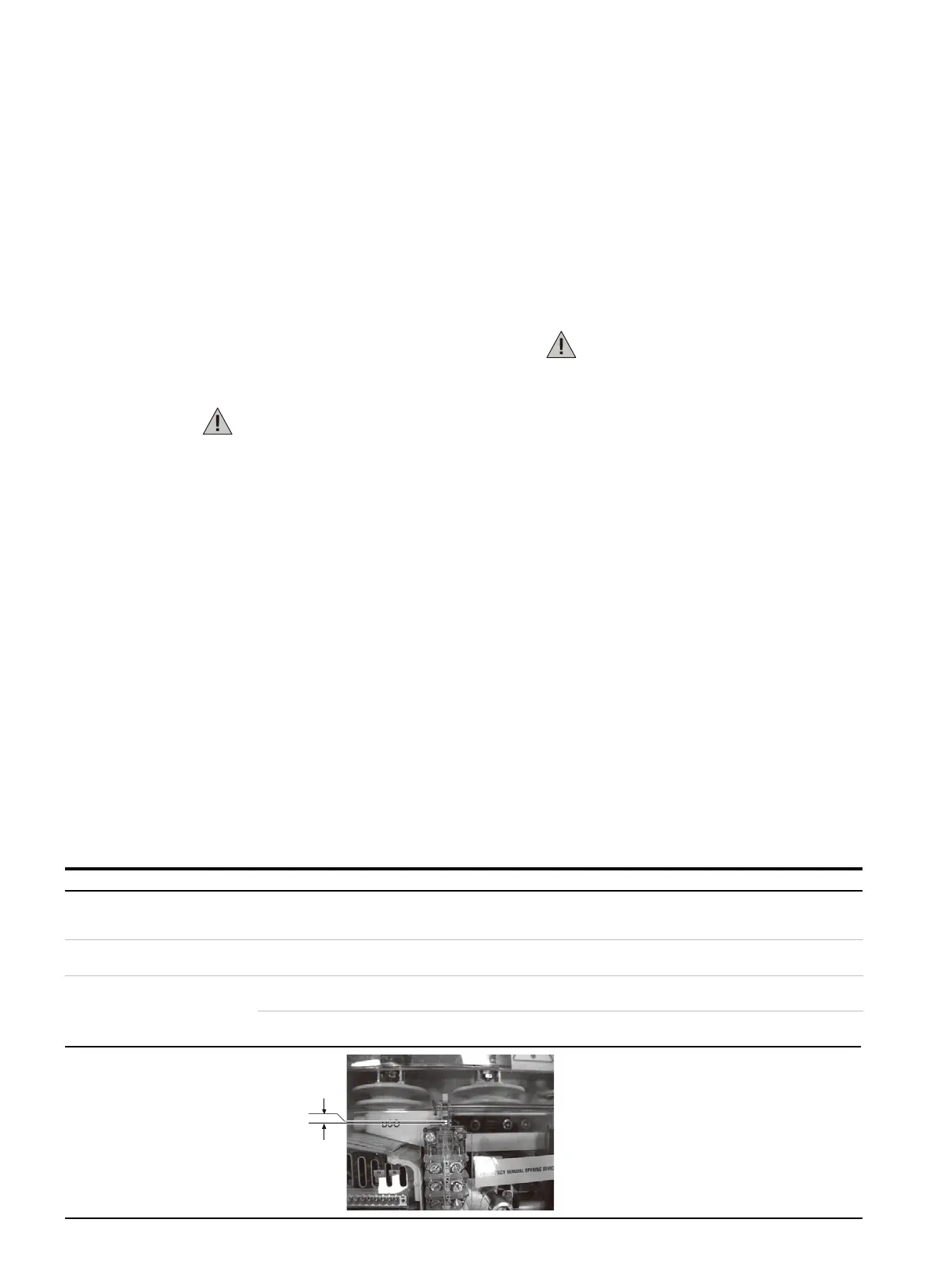
0,5 mm
—
Table. 1
Item inspected Procedure Positive check
1. Insulation resistance
The insulation resistance should be at
least 50 Mohm.
Carry out a few closing and opening operations of the
contactor.
Operations and signals normal.
3. Auxiliary circuits
Operations and signals normal.
Tighten the fixing screws.
Medium voltage circuit use lower letter, with and not Width With
a 2500 V megger, measure the insulation resistance between
the phases and the exposed conductive part of the circuit.
Check that the connections to the control circuits are
correct: proceed with the relative power supply.
With the contactor open, check that the thickness between
the body of the contact and the stem is 0.5 mm.
2. Drive open/closed indicator,
operation counter (if provided)

 Loading...


