Medium voltage products
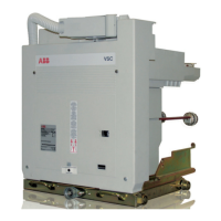
V-Contact VSC
Installation and service instructions
7.2/12 kV - 400 A
For your safety! 1
I. Introduction 2
II. Programme for environmental protection 2
III. Application of the standards for X-ray emission 3
IV. Safety information 3
V. Qualified personnel 3
VI. Interventions in the field 3
1. Description 4
1.1. “MAC” magnetic drive 4
1.2. Versions available 5
1.3. Characteristics 6
1.4. Weights and overall dimensions 6
1.5. Performances 8
1.6. Contactor auxiliary contacts 8
1.7. Compliance with Standards 9
1.8. Protection against short-circuit 9
2. Checking on receipt 10
3. Handling 11
3.1. Handling and lifting using a crane 12
4. Storage 13
5. Installation 14
5.1. General 14
5.2. Installation and operating conditions 14
5.3. Normal conditions 14
5.4. Special conditions 14
5.5. Overall dimensions 15
5.6. Assembly and making the connections 21
5.7. Description of the closing and opening operations 30
5.8. Manual emergency opening operation 33
6. Putting into service 34
6.1. General procedures 34
6.2. Racking the VSC/P contactor in and out 35
7. Maintenance 36
7.1. General 36
7.2. Handling the MAC-R2 electronic card 36
7.3. Inspection 37
7.4. Servicing 38
7.5. Servicing following a short-circuit or overload 38
7.6. Repairs 38
7.7. Instructions for dismantling or replacing fuses 39
7.8. Replacement of the contactor fuses 40
7.9. Mounting and dismantling the short-circuit busbar 43
7.10. Putting the contactor back into service 43
7.11. Checking the degree of vacuum of the interrupter 43
8. Spare parts and accessories 44
8.1. List of spare parts 44
9. Product quality and environmental protection 44
This instruction booklet refers to the following models:
VSC/F-VSC/FN-VSC/P-VSC/PG-VSC/PN-VSC/PNG
VSC-S/F-VSC-S/G-VSC-S/PG-VSC-S/PNG
NEPSI.COM - Northeast Power Systems. Inc.

 Loading...