21
5.6. Assembly and making the
connections
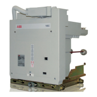
5.6.1. Fixed contactors
WARNING
Dangerous voltages. Risk of death,
serious injury to people, damage
to the apparatus or other objects.
Remove the power supply, ground
and put all the power and control
voltage sources under safe
conditions before starting the
work on this or any other electrical
apparauts.
Installation must only be carried
out by qualified personnel.
Introduction
Before carrying out any installation operations:
•Testallthepowerterminalstocheckthattheyarenot
supplied with voltage. Only use high voltage testing
equipment approved for checking the voltage on the power
terminals. Do not attempt to measure the high voltage
(above 600 volt) with a volt-ohm/meter.
•Checkallthecontrolandsecondarycircuitterminalswitha
voltmeter to ensure that all the control and secondary input
voltage sources have been turned off.
•Connectthesafetyearthingtothepowerterminalsafter
having turned the power supply to the system off and
before working on the apparatus.
•Carryoutalltheoperationsforturningoffthevoltageand
earthing according to the established safety procedures.
Power circuit
General precautions
– Check that the connections of the fixed contactor or the
isolating contacts of the withdrawable contactor are clean
and free of any deformation caused by shocks received
during transport or storage in the warehouse.
– Select the cross-section of the conductors according to
the service current and the short-circuit current of the
installation.
– Preparespecialpoleinsulators,neartheterminalsofthe
contactor,sizedaccordingtotheelectrodynamicforces
deriving from the short-circuit current of the installation and
avoid stressing the connections laterally.
Surface treatment of the connections
The connections can either be made of bare copper or bare
aluminium.Inanycase,itisalwaysadvisabletosilver-plate
the contact surfaces. The surface treatment must have a
constant and even thickness.
Assembly procedures for fixed contactors
– Checkthatthecontactsurfacesoftheconnectionsareflat,
andarefreeofanyburrs,tracesofoxidationordeformation
caused by drilling or impacts received.
– Carry out the operations indicated on the contact surface of
theconductor(silver-platedcopper):
- clean with a rough dry cloth
-onlyinthecaseofobstinatetracesofoxidation,clean
with a very fine grain emery cloth taking care not to
remove the surface layer
- ifnecessary,restorethesurfacetreatment(consultABB)
- put the connections in contact with the contactor
terminals,takingcaretoavoidmechanicalstresses
produced,forexample,bytheconductorbusbarsonthe
terminals themselves.
– Interpose a spring and a flat washer between the head of
the bolt and the connection.
– The use of bolts according to DIN class 8.8 Standards is
recommended,alsoreferringtowhatisindicatedinthe
table.
– Inthecaseofcableconnections,strictlyfollowthe
manufacturer’sinstructionsformakingtheterminals.
Bolt Recommended tightening torque (1) Without lubricant
M6 10.5 Nm
M8 23 Nm
M10 50 Nm
M12 86 Nm
(1)Thenominaltighteningtorqueisbasedonafrictioncoefficientofthethreadof0.14
(distributedvaluethethreadissubjectedtowhich,insomecases,isnotnegligible).
TakeintoaccountthedeviationsfromthegeneralStandardstable(forexample,for
contact systems or terminals) as foreseen in the specific technical documentation.
The thread and surfaces in contact with the heads of bolts must be slightly oiled or
greased,soastoobtainacorrectnominaltighteningtorque.
The tightening torques indicated can only be applied to metal parts.
Earthing and cabling procedures
VSC conforms to level 3 of the IEC 61000-4-x EMC
Standards.Withregardtomediumvoltageswitchgear,the
plants where the VSC contactors are to be installed must
conform to the IEC 60694:2002-01 and IEC 62271-1 ed. 1.0
Standards,toensureadequateelectromagneticimmunity.
Pay great attention during earthing and cabling operations
of the auxiliary circuits. Follow the procedures indicated. For
furtheradvice,pleasecontacttheABBServiceoffice.
NEPSI.COM - Northeast Power Systems. Inc.

 Loading...