 Loading...
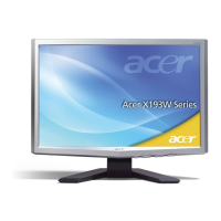
Do you have a question about the Acer X193W and is the answer not in the manual?
| Pixel pitch | 0.284 mm |
|---|---|
| Display diagonal | 19 \ |
| Display resolution | 1440 x 900 pixels |
| Vertical scan range | 56 - 60 Hz |
| Horizontal scan range | 24 - 80 kHz |
| Viewable size, vertical | 255 mm |
| Contrast ratio (typical) | 2000:1 |
| Viewable size, horizontal | 408 mm |
| Viewing angle, horizontal | 160 ° |
| Display brightness (typical) | 300 cd/m² |
| Certification | UL, CUL, TUV/GS, T-Mark, ISO9241-3/-7/-8, FCC/B, VCCI, CE, C-tick, BSMI, WHQL, ISO 13402-6 |
| Product color | Black |
| Market positioning | - |
| Cable lock slot | Yes |
| Cable lock slot type | Kensington |
| Panel mounting interface | 100 x 100 mm |
| Power requirements | 100 - 240 VAC, 50 - 60 Hz |
| Power consumption (off) | 1 W |
| Power consumption (standby) | 2 W |
| Power consumption (typical) | 37 W |
| Depth (with stand) | 163.7 mm |
|---|---|
| Width (with stand) | 454.3 mm |
| Height (with stand) | 359.2 mm |
| Weight (without stand) | 4400 g |
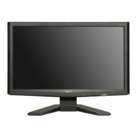
Overview of the monitor's capabilities and purpose.
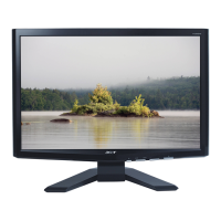
Details on LCD technology, space-saving, and power efficiency.
Specifies test conditions and electrical parameters for the monitor.
Lists general specs like display area, pixel pitch, contrast, response time, and dimensions.
Details general specifications and absolute maximum ratings for the LCD panel.
Covers contrast, response time, luminance, color chromaticity, and viewing angle performance.
Lists supported display modes, resolutions, and refresh rates for compatibility.
Illustrates the main components and signal flow within the monitor system.
Shows the schematic and connections of the monitor's main circuit board.
Visual representation of the monitor's software logic and decision points.
Explains the steps and conditions described in the software flow chart.
Diagram showing the physical placement of components on the main board.
Steps to connect the monitor to a host system, including video and power cables.
Instructions for attaching and detaching the monitor's base stand.
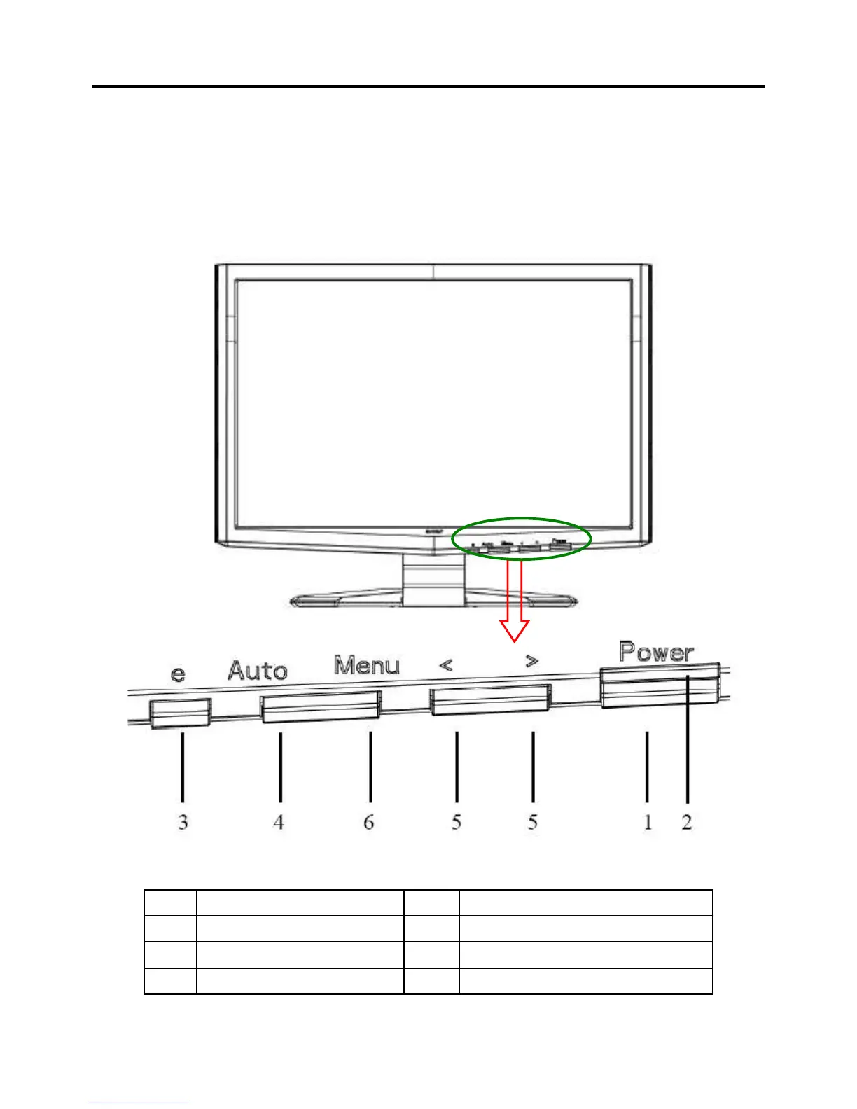
Identifies and describes the buttons and indicators on the monitor's front panel.
Detailed explanation of each button's function and operation on the front panel.
Describes the Acer eColor Management system and its preset modes.
Guides the user on navigating the OSD menu to adjust picture settings.
Explains how to fine-tune picture settings like contrast, brightness, and color.
Details horizontal/vertical positioning, color temperature, RGB intensity, and language settings.
Describes OSD positioning, timeout, input selection, information display, reset, and exit options.
Explains common OSD messages like "Auto Config" and "No Signal".
Discusses the Acer logo display, Plug & Play, DDC2B, and power saving features.
Provides guidelines on selecting and using the correct power cord for different regions.
Step-by-step guide for disassembling the monitor for maintenance.
Instructions for removing the monitor's back cover and related hooks.
Steps to remove the keyboard and the front bezel of the monitor.
Procedure for removing the monitor's LCD panel, including screw locations.
Steps to remove the main board, audio board, and power board.
Troubleshooting steps for issues where the monitor does not power on.
Troubleshooting steps for when the screen displays no image.
Diagnosing issues with the panel power circuit and keypad board functionality.
Troubleshooting steps for when the monitor screen has no backlight.
Details the pinout and functions of the 15-pin VGA connector.
Details the pinout and functions of the 24-pin DVI connector.
Guidance on ordering replacement parts and referencing regional lists.
Visual breakdown of the monitor showing all components and their assembly.
Pictures and descriptions of key monitor components like the base, shield, and panel.
Pictures and descriptions of the power board and main board components.
Detailed circuit diagram for the monitor's main logic board.
Circuit details for the microcontroller (MCU) and scalar IC.
Circuit diagram illustrating the power supply and voltage regulation components.
Circuit diagram for the LVDS output and control signals.
Detailed schematic of the power board, including input and output circuits.
Schematic diagram of the monitor's inverter circuit for backlight control.