Calibration Procedures 1
Performance Verification Tests
U1231A/U1232A/U1233A Service Guide 11
9
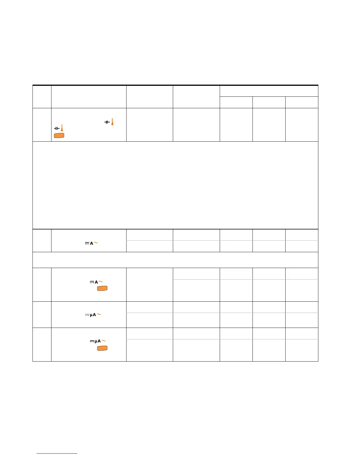
Tem pera ture
[6]
While the
rotary switch is in the or
position, press the
key once.
–40 °C to 1372 °C 0 °C - - ±1.0 °C
[6] Ensure that the ambient temperature is stable within ±1 ºC. Ensure that the multimeter is placed in a controlled
environment for at least 1 hour before you proceed to ensure that the multimeter’s internal reference junction sensor and
input terminal are stabilized at the same environment. Keep the multimeter away from any ventilation exit.
Differences in ambient compensation between the calibrator and multimeter may cause some deviations shown between
the readings of the calibrator and multimeter. Placing the multimeter close to the output terminal of the calibrator will help
reduce this deviation.
Keep the thermocouple test lead as close to the multimeter as possible.
Do not touch the thermocouple test lead after connecting it to the calibrator. Allow the connection to stabilize for at least
another 15 minutes before performing the measurement.
10
DCA
[7]
Turn the rotary
switch to the position.
6 A 6 A - ±0.063A ±0.063A
10 A 10 A - ±0.13 A ±0.13 A
[7] CAUTION: Connect the calibrator to the multimeter's A and COM terminals before applying the 6 A and 10 A input.
11
ACA While the rotary
switch is in the
position, press the key
once.
6 A 6 A, 500 Hz - ±0.093 A ±0.093 A
10 A 10 A, 500 Hz - ±0.18 A ±0.18 A
12
DCμA Turn the rotary
switch to the
position.
60 μA60 μA-±0.62 μA ±0.62 μA
600 μA600 μA-±6.2 μA ±6.2 μA
13
ACμA While the rotary
switch is in the
position, press the key
once.
60 μA60 μA, 500 Hz - ±0.93μA ±0.93μA
600 μA600 μA, 500 Hz - ±9.3 μA ±9.3 μA
Table 1 - 2 Performance verification tests (continued)
Step Test function Range 5520 output
Error from nominal 1 year
U1231A U1232A U1233A

 Loading...


