2 Making Measurements
24 U2000 Series Operating and Service Guide
Measurement Accuracy and Speed
With U2000 Series USB power sensors, the range can be set either
automatically or manually. Use auto- ranging when you are not sure of the
power level you are about to measure.
The DC coupling of the U2004A USB power sensor input allows excellent low
frequency coverage. However, the presence of any DC voltages mixed with the
signal will have an adverse effect on the accuracy of the power measurement,
see
on Page 46.
Setting the Range
There are two manual settings, “LOWER” and “UPPER”. The LOWER range
uses the more sensitive path and the UPPER range uses the attenuated path in
the U2000 Series USB power sensors (see
Table 2- 1).
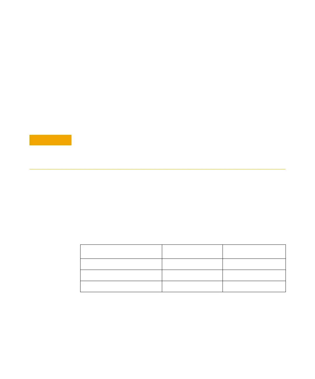
Tabl e 2- 1 Sensor Ranges
The default is “AUTO”. In AUTO the range crossover value depends on the
sensor model being used (see
Table 2- 2).
To prevent damage to your sensor, do not excess the power levels specified in the
section
“Maximum Power” on page 42.
The U2004A USB Power Sensor is DC coupled. DC voltages in excess of the maximum
value (5 VDC) can damage the sensing diode.
Sensor LOWER range UPPER range
U2000A, U2001A, U2002A, U2004A –60 dBm to –10 dBm –10 dBm to +20 dBm
U2000H, U2001H, U2002H –50 dBm to 0 dBm 0 dBm to +30 dBm
U2000B, U2001B –30 dBm to +20 dBm +20 dBm to +44 dBm

 Loading...


