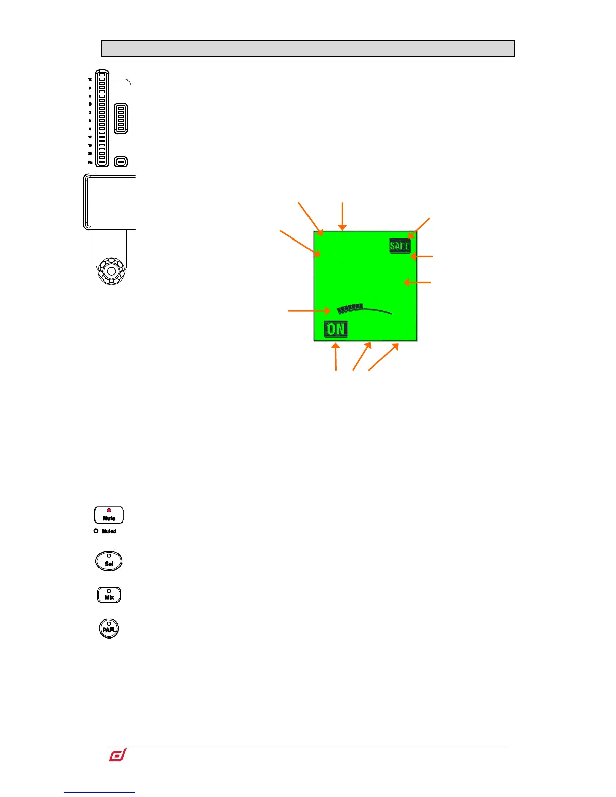
3.3 Fader strip
Meter – 22-segment signal meter and 6-segment gain reduction meter. The meter
displays audio signal activity for the channel.
The red peak indicator lights to warn that the signal is within 3dB of clipping. It is multi-
point sensing which means it detects peak activity at several points in the signal path.
If it lights before the rest of the meter, check signal activity in the processing screen.
To set the global meter source point for Input channels and Mix masters, hold
down Setup and touch the main screen area in the Meters / Inputs or Meters /
Mix screen.
LCD Display – Displays information about the channel, including name and colour.
Strip rotary – Their function is
selected using the strip rotary mode
keys as described earlier in this
chapter. The rotaries can control
preamp Gain, Pan, Sends to the
active Mix, and 4 assignable
functions. The colour of the rotary
LED matches the active function
e.g. red for Gain, yellow for Pad; it
follows the colour of the active Mix
when in Sends mode. The value is
displayed in the LCD display.
Mute – Turns off the channel signal. Affects the main mix, pre-fade and post-fade
sends. The Muted LED lights when the channel is muted by a DCA or Mute Group.
Sel – Selects the channel for use with the Processing and Routing screens. The
channel strip controls become active to control processing for the channel.
The currently selected channel is displayed in the top left corner of the
Processing screen.
Mix – Puts the send levels and assignments of the associated channel or masters onto
the fader strips (or strip rotaries when rotaries are in Sends mode). See the next
paragraph for examples of use.
The currently active Mix is displayed in the top right corner of the Processing
screen. Press an active Mix key to return to the main mix.
PAFL – Sends the channel signal PFL (pre-fade listen) or AFL (after-fade listen) to the
headphones and monitoring system. Preferences for the PAFL system are set using
the Surface / Audio / PAFL screen.
Use the LCD Display Mode
keys to display the user-
defined channel Name, the
fader position in dB, the DSP
channel number, or the I/O
socket identifier of the
patched source / destination.
I/O sockets are displayed as
follows:
R-nn = MixRack
S-nn = Surface
DXn-nn = DX Expander port
number and socket number
USB = USB playback/recording
Pn-nn = I/O Port number and
channel number
FX-n = RackExtra FX unit
number
SigGen = Internal Signal
Generator
 Loading...