8
DR128 SERVICE MANUAL
ORDERING A DR128 UNIT
To order a new unit please specify the model number and AC mains voltage required.
MODEL DESCRIPTION ORDER CODE
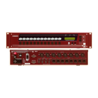
DR128 12 Inputs 8 outputs DR128/volts
ORDERING AN OPTION
To order an option please specify the model number.
DESCRIPTION ORDER CODE
DR1 DSP expander card DR1-DSPX
DR1 DSPD delay expander card DR1-DSPD
DR1 SYSNET option DR1-SNET
MANUALS, SOFTWARE AND SUPPORT DOCUMENTATION
DESCRIPTION ORDER CODE
DR128 User Guide AP2973
DR128 Service Manual AP2974
DR128 Brochure AP2903
DR128 WinDR Disk (1 of 2) 002-272
DR128 WinDR Disk (2 of 2) 002-273
SERVICE TOOLS
The tools required to service the DR128 range of products are standard to an electronics service workshop and
are easily obtainable. The following items are necessary for disassembly and service access:
1-point Crosshead screwdriver (M3, 4AB) AT0004
2-point Crosshead screwdriver (M4, 6AB) AT0002
5mm AF Nutdriver
ORDERING AN ASSEMBLY
The following assemblies for the DR128 are supplied fully tested. Please quote the description and order code
for the part required.
Printed circuit (PCB) assemblies:
Power supply PCB assembly (inc heatsink) 002-205
Front panel PCB assembly (exc LCD display) 002-187
CPU microprocessor PCB assembly 002-184
Mic connector (Upper) PCB assembly 002-185
Line / Output connector (Lower) PCB assembly 002-186
IDC connector harnesses:
40 way Master harness AL2711
26 way front panel harness AL2713
26 way Mic / Line harness AL2712
9 way Mic / Line power harness AL2705
9 way CPU power harness AL2706
26 way LCD display harness AL2714
Spare parts
 Loading...