ALLEN & HEATH
GL4000 SYS-LINK OPTION
4
Refering to fig. 3, fit the 4 self adhesive foam pads (F) in the positions indicated next to the front panel flange.
ww
ww
w
Remove the 8 screw fixings already partly screwed into the D type connectors on the SYS-LINK ribbon
harness assembly and place to one side.
vv
vv
v
uu
uu
u
The Input channel circuit board assembly next to GROUP 1 circuit board can now be removed and placed
on the adjacent Input channels. Take care not to stretch the fader wires that are still connected.
Refering to fig. 2, disconnect the MAIN HARNESS (E) plugged into the connectors mounted along the edge
of the circuit boards from INPUT CHANNEL 1 to GROUP 2.
tt
tt
t
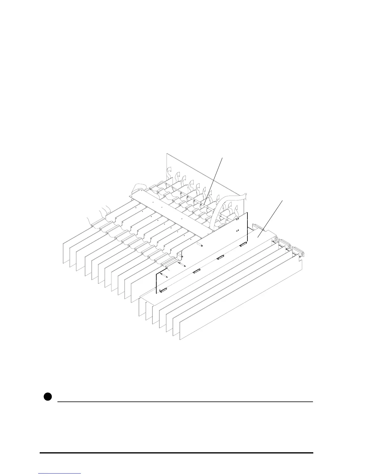
fig. 3
F
F
F
F
SYS-LINK
CIRCUIT
BOARD
INPUT CHANNEL
CIRCUIT BOARD
ASSEMBLY
SYS-LINK HARNESS
CONSOLE FRONT
GL4000-824 inverted with the input connector circuit board assembly removed.
FITTING THE SYS-LINK RIBBON HARNESSES :
Place the SYS-LINK circuit board assembly next to the GROUP 1 circuit board with the harness and ribbon
cables to the rear of the console. see fig. 3.
Slide the pre-formed SYS-LINK ribbon harnesses toward the back of the console and down the gap
between the Channel Input circuit boards and the back panel. Check the connectors are mounted into the
correct apertures on the rear panel.
Mount the 4 D type connectors using the 8 hex screws provided. see
vv
vv
v
11
 Loading...